I can now program FPGA!! Well, I can copy someone else's example code and get it to work on my device. Check out this excellent video which shows how to write VHDL to make an LED blink:
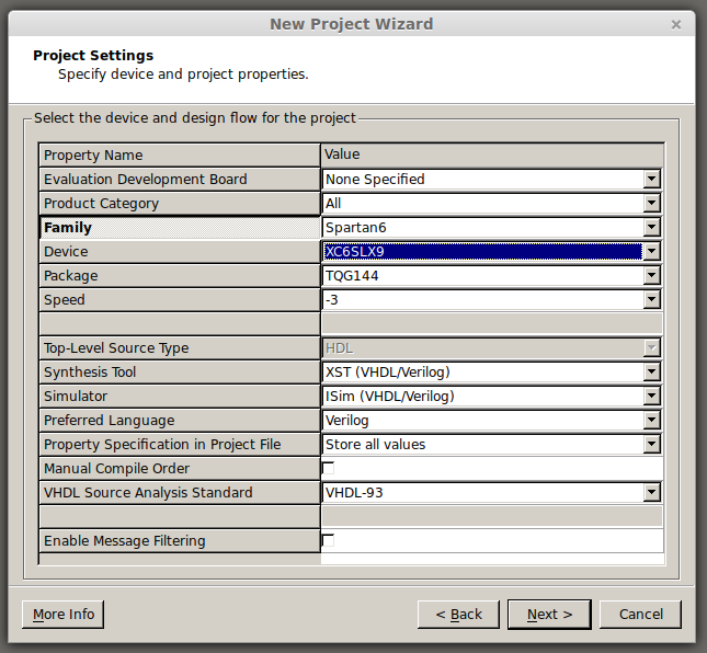
When following that tutorial you simply need to select the correct hardware:

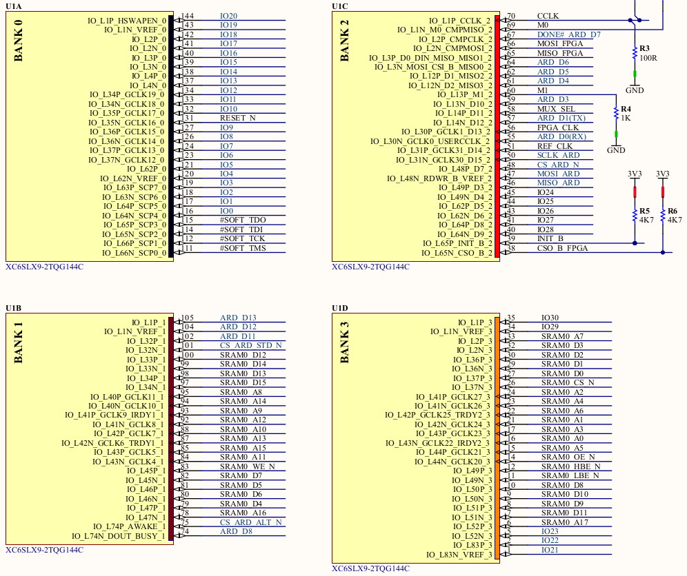
For the pinout you need to look at the FPGA Development Board PDF schematics found here:
https://github.com/sfgit/FPGA_Arduino_Shield/tree/master/Design%20Files/PDFs
The pinouts are shown on page 6:

I know from other parts of that document that the crystal oscillator is connected to the FPGA_CLK signal and the LED I'm targeting is connected to IO12. These correspond to P56 and P134 which are used in the pins file.
Here is the code that allowed me to get an LED blinking. Note that this is designed for a 50MHz oscillator but this board actually has a 20MHz oscillator. For this example I don't care about the timing error.
LED_Blink.vhd:
library IEEE;
use IEEE.STD_LOGIC_1164.ALL;


use IEEE.STD_LOGIC_ARITH.ALL;
use IEEE.STD_LOGIC_UNSIGNED.ALL;


entity LED_Blink is
	port (
		CLK_50MHz: in std_logic;
		LED: out std_logic
	);
end LED_Blink;


architecture Behavioral of LED_Blink is
	signal Counter: std_logic_vector(24 downto 0);
	signal CLK_1Hz: std_logic;
begin


	Prescaler: process(CLK_50MHz)
	begin
		if rising_edge(CLK_50MHz) then
			if Counter < "1011111010111100001000000" then
				Counter <= Counter + 1;
			else
				CLK_1Hz <= not CLK_1Hz;
				Counter <= (others => '0');
			end if;
		end if;
	end process Prescaler;

	LED <= CLK_1Hz;


end Behavioral;
pins.ucf:
NET "CLK_50MHz" LOC = "P56";
NET "LED" LOC = "P134";
That's it! Hello Word!
 Mike Szczys
Discussions
Become a Hackaday.io Member
Create an account to leave a comment. Already have an account? Log In.