 bveina
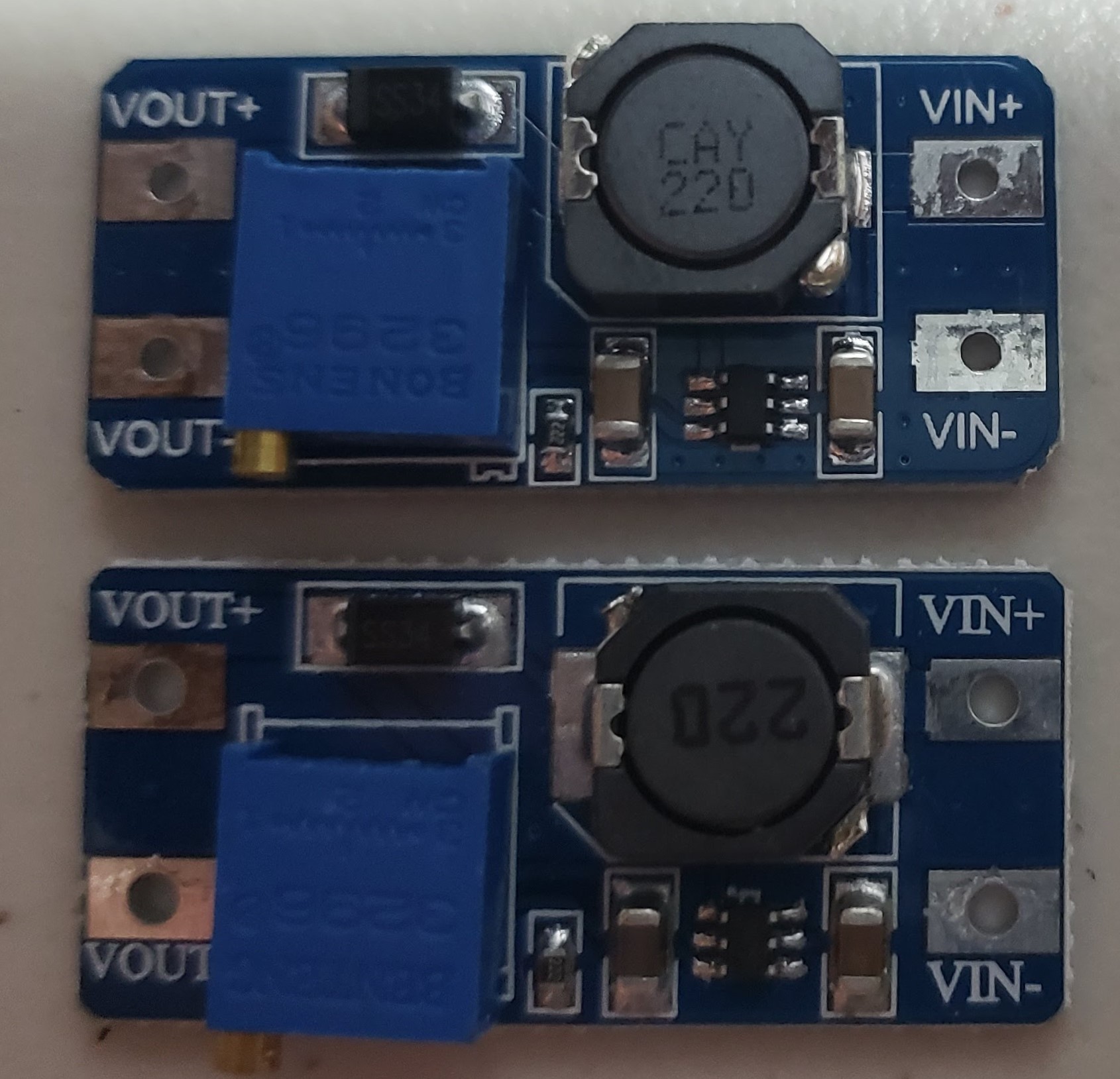 | 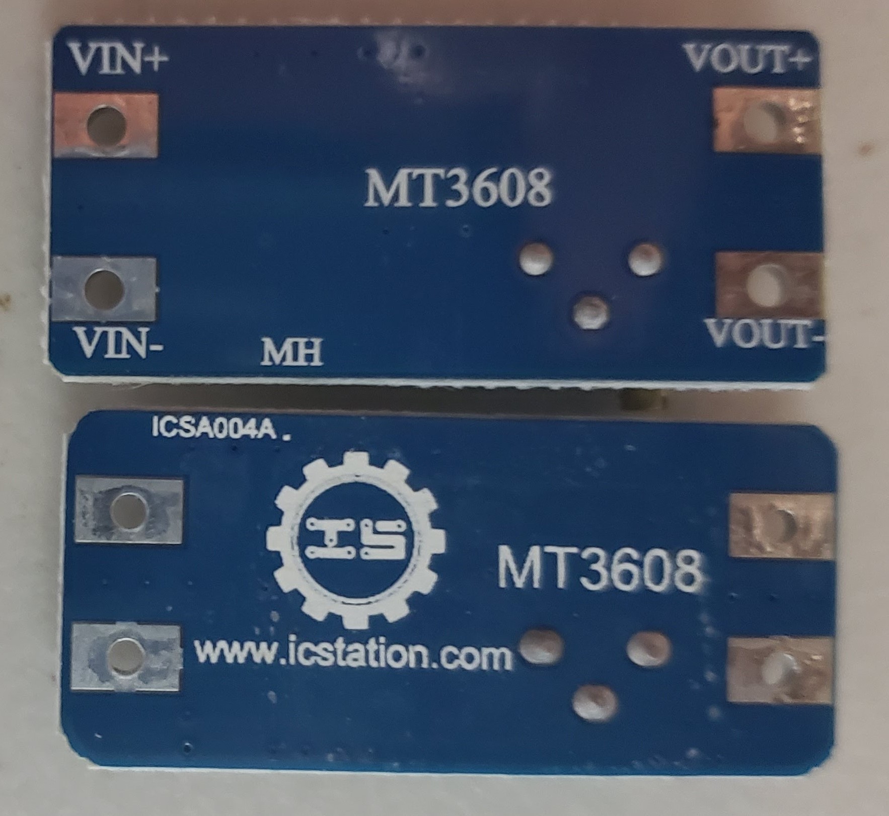 |
One of these boost converters works, the other appears to not work. can you spot the difference?
the centerpiece could draw a peak of 750mA. so ive been in search of a boost converter to take a Lithium ion pack at 3.7V nominal and boost it up to the 5V for the APA102 addressable Leds. i bought a few candidates on ebay and tested them out. i really liked this one based on the MT3608 step up converter by aerosemi. its dead simple and should handle 2 amps max. so i bought 20 from aliexpress and when they arrived set about to test them all; and Every Single One FAILED.
As a teacher, if one of my students came to me and said 20 units all were broken...i'd be skeptical to say the least. so i brought in a friend to double check my setup, both of us agreed they SHOULD work. but it was obvious that the IC was not switching, and therefor the inductor was at DC. so 3.7V was present at Vin. and there was a small drop at the diode.

My first guess was the IC; was i counterfit? was it ESD damage? so i exchanged the ic's from the working board to the dead board and vice-versa. No change, in either board. the one that used to work still worked. the one that didnt work continued to not work. we went down the list of components
- IC - No Change
- Caps (10uF) - no change
- Shottky Diode - No Change
- 2.2K ohm resistor - No Change
- 22uH Inductor - No Change
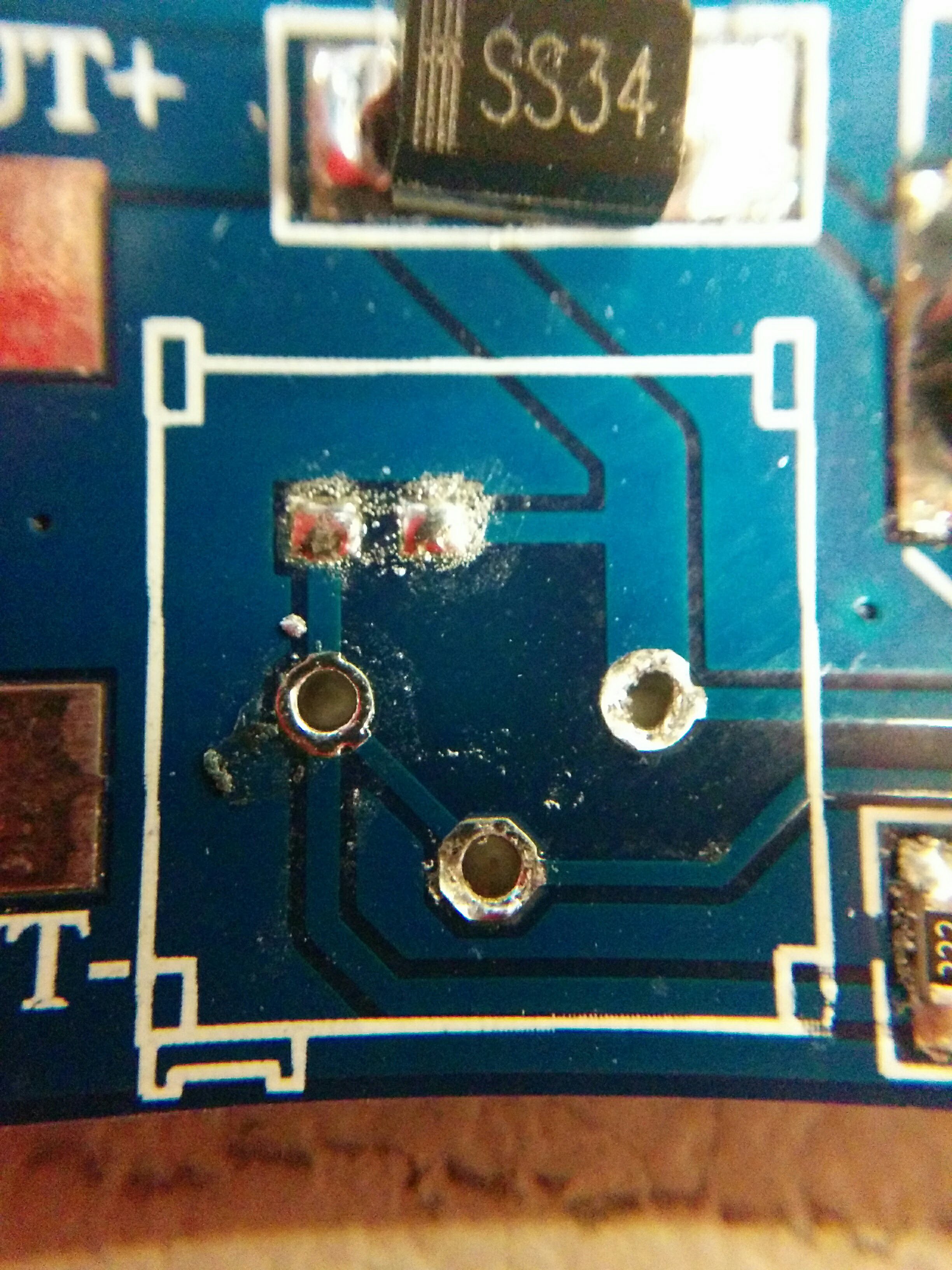
- Potentiometer - No Ch-WAIT WHAT??
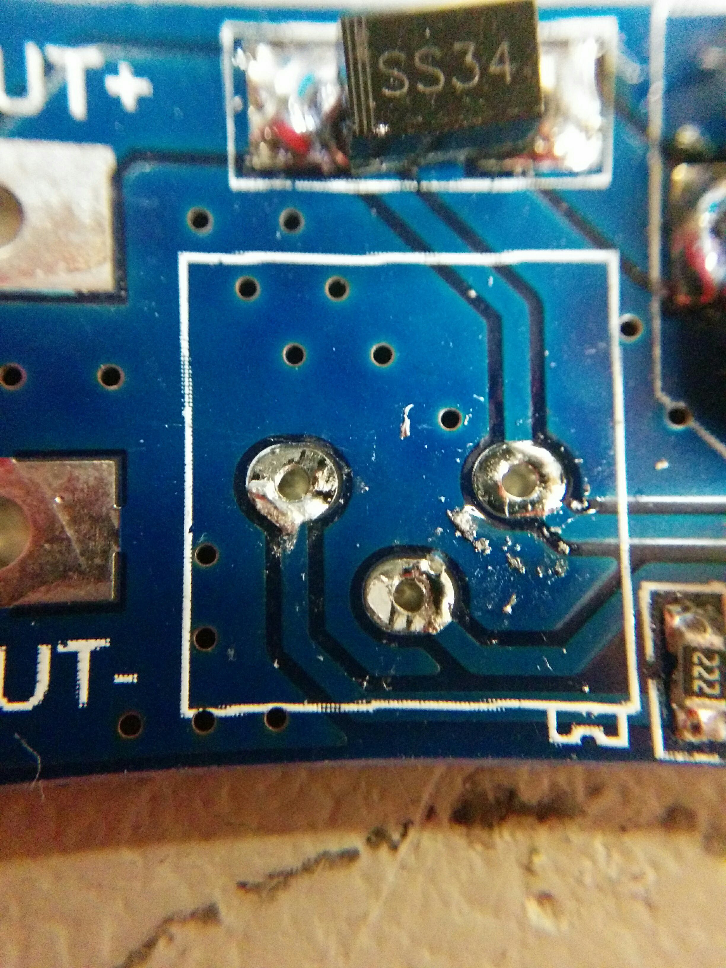 |  This one always worked |
Well that's different what the hell is going on?
I removed all the items from both the working and non-working boards then reverse engineered both boards into eagle.
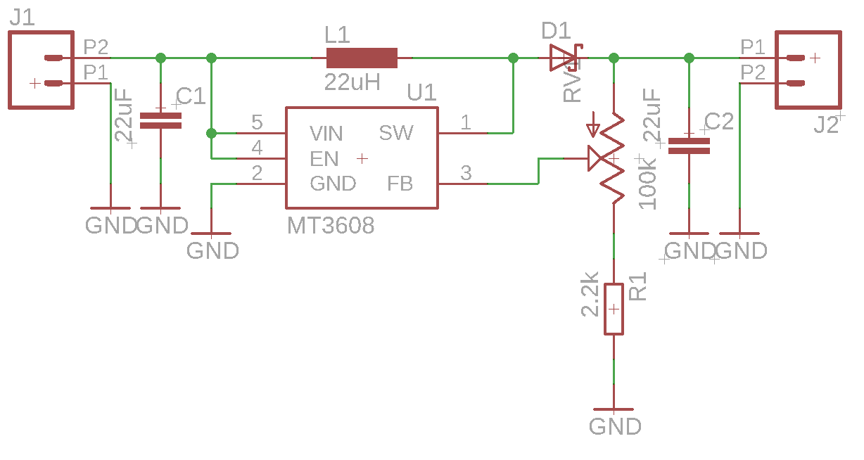 |
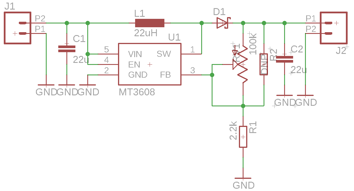 Functional  Application circuit from the datasheet Application circuit from the datasheet |
The obvious difference between the two is one uses the potentiometer as a three terminal device and the other uses the potentiometer as a rheostat. On the surface this didn't really seem to explain the problem.
so in either case
- If the potentiometer is all the way "left" we would have 0.6 V *(1+ 0/102k) = 0.6V
- If the potentiometer is all the way "right" we would have 0.6V * (1+100k/2k) = 27.8V
This basically matches with the data sheets min and max voltages.
at this point my friend let me in on the secret. let me illustrate using wolfram alpha to plot the output voltage as a function of the percentage of the pot from off to full.
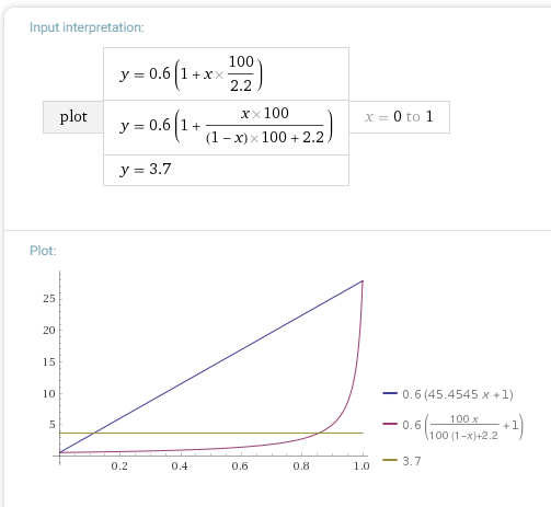
and there it is as plain as the nose on my face; the "working" one has a linear response over the 30 turns of the potentiometer. but the "non-working" version presents an exponential response basically it wont even turn on until you're 85% on.
In the end it wasn't cheap manufacturing or counterfeit parts; it was a PEBKAC error. All i needed to do was turn the pot another 20 turns and i began to see the converter boost up to my required voltage. i prefer the linear response though so shorting the two terminals of the the potentiometer nicely solves that problem.
with that out of the way I can now run the entire centerpiece off of battery power.
more on how i created this in the next post
Discussions
Become a Hackaday.io Member
Create an account to leave a comment. Already have an account? Log In.