Today UPS arrived with my Digikey order containing all the components to build revision 1 of the HydroPWNics hardware. I am hoping to solder and test the hardware this week, and get each board functioning/ready for development. If there are any problems or mistakes in the design, I'm going to attempt to modify the PCBs with wire and trace cutting, and if that cant render the current hardware revisions functional next week will be dedicated to revising the PCBs. If the PCBs are functional or repaired to function the plan is to spend next week on the embedded software. Here is what the pile of parts looked like:
So yeah yay parts! So as for populating these PCBs successfully without damaging components I have sort of a protocol I follow for populating boards. With a prototype I like to do manual assembly placing each component on one at a time under a stereo microscope. I like to ensure that every single component is soldered on perfectly to prevent shorts and keep components well secured to the pads. Now when the PCB is populated I do it in stages/sections rather than solder on all the components, cross my fingers and turn on the power. I found that that method can result in blown components and that's not fun for anyone, components cost money and can be difficult to remove depending on the package. The first stage/section thats populated is the power supply, whatever it is composed of in the case of these board a decoupling cap and a regulator. After the power supply is populated, I inspect it for shorts under the microscope and power it on. The goal is to debug the power circuit and make sure it is function correctly. The next thing I do is manually test all the pads that should be receiving power and make sure they are recieving the correct voltage (some designs have more than one voltage). In the case that the design has a more complex power circuit such as the module hub with its two regulators, then the process is the same except one regualtor is populated and tested before the other. The next stage for population and testing really depends on the topology of the PCB, in this case the hydroPWNics boards are microcontroller boards like most of my projects tend to be. In this case the next thing I populate and test is the micro controller and its supporting passive components everything it needs to boot up. After the microcontroller is soldered in place with its supporting components I power it up and attempt to program the micro, if it is succesfful I just populate the rest of the board if not consult the datasheet and figure it out! Thats basically my PCB population protocol I'll try to cover each section of the population of each board in the next project log.
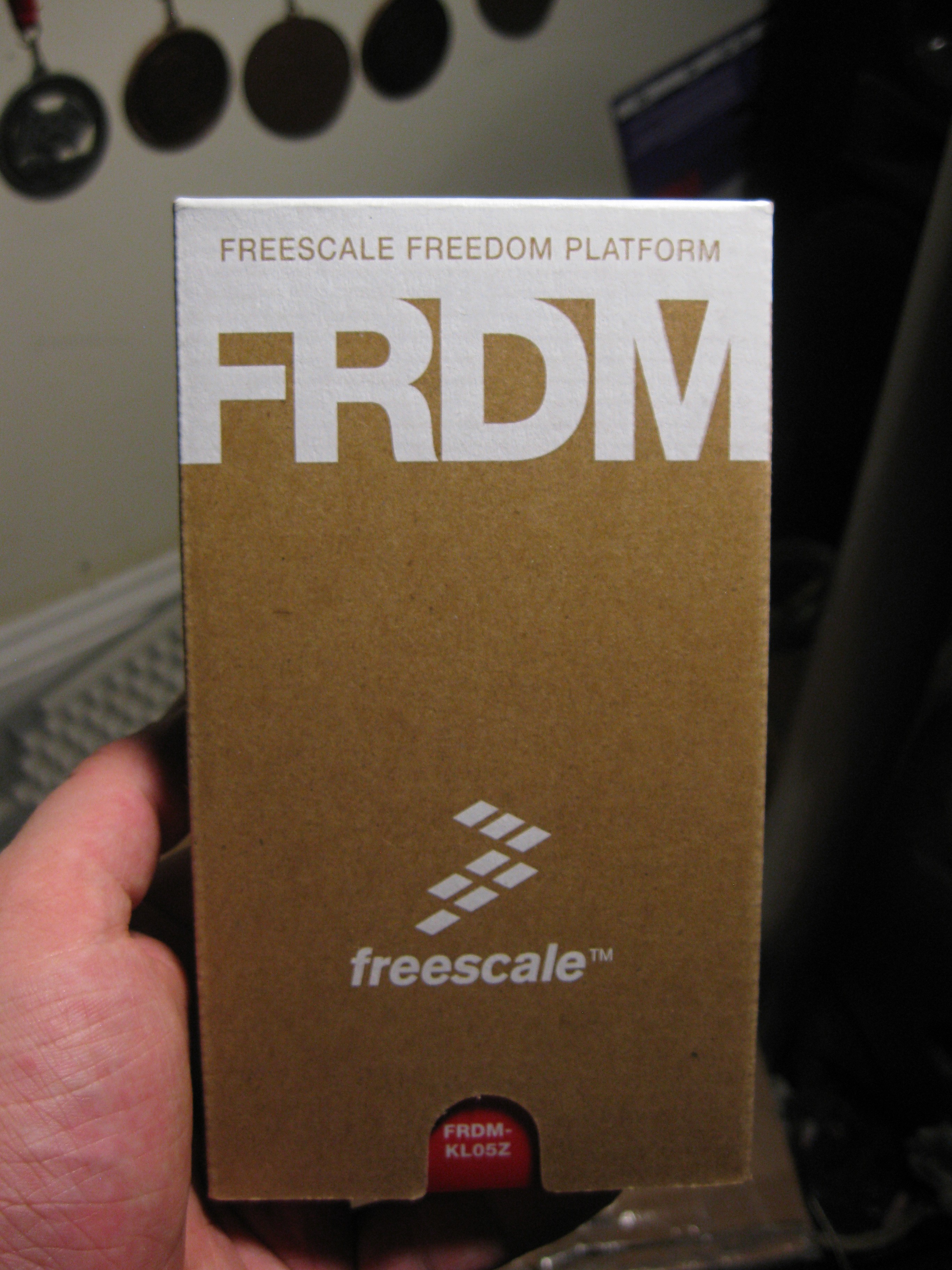
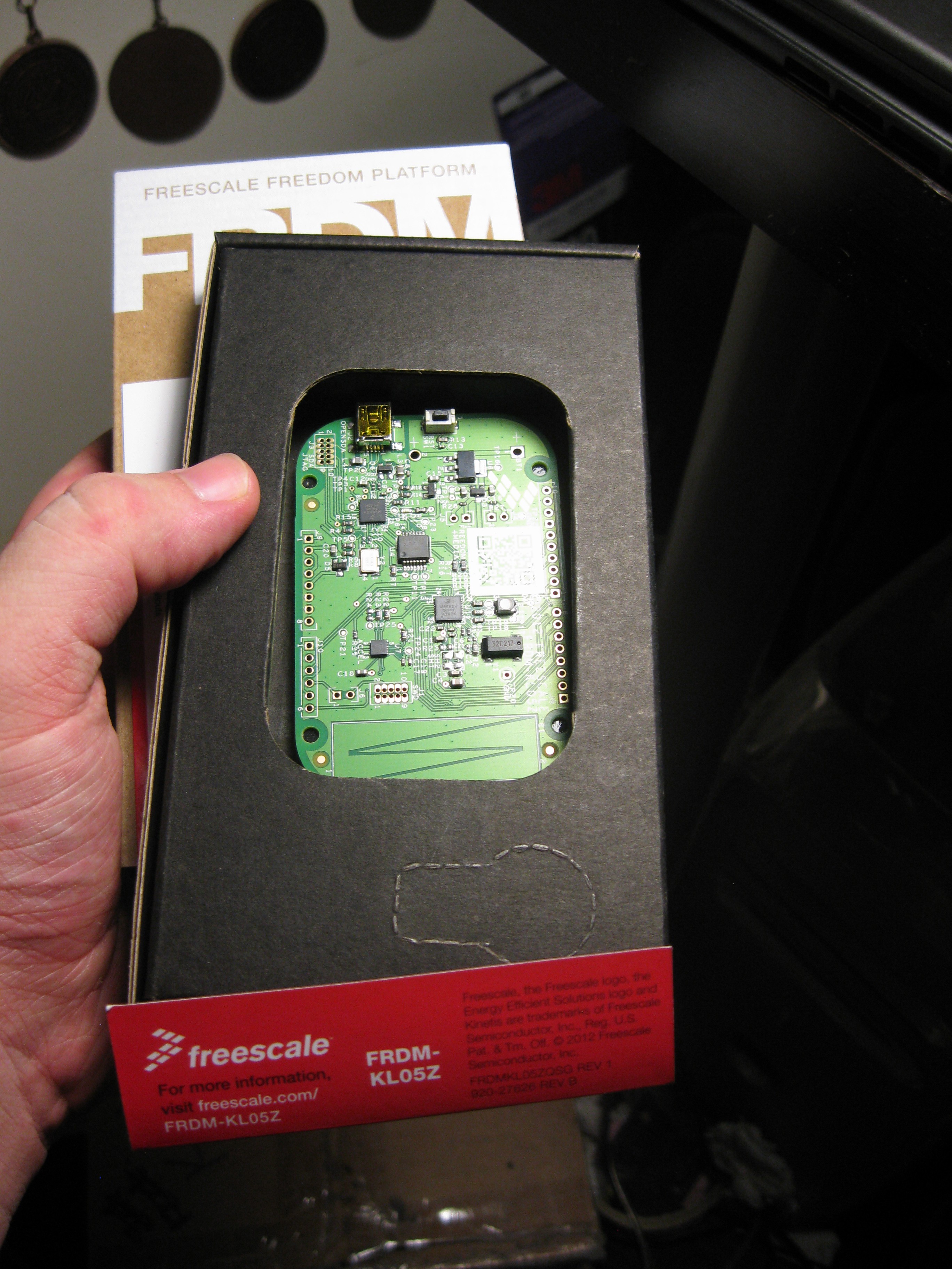
Amongst the components in the box from digikey was something else. I also purchased a FreeScale FRDM-KL05Z Freedomboard, this will function as a development tool acting as a dev board and programmer for the two sensor modules. I do also believe I will be able to program the Module Hub with the OpenSDA debugger built into the Freedomboard but I have yet to test it. Anyways I thought the packaging for the little board was pretty neat so here a picture:
Open Box
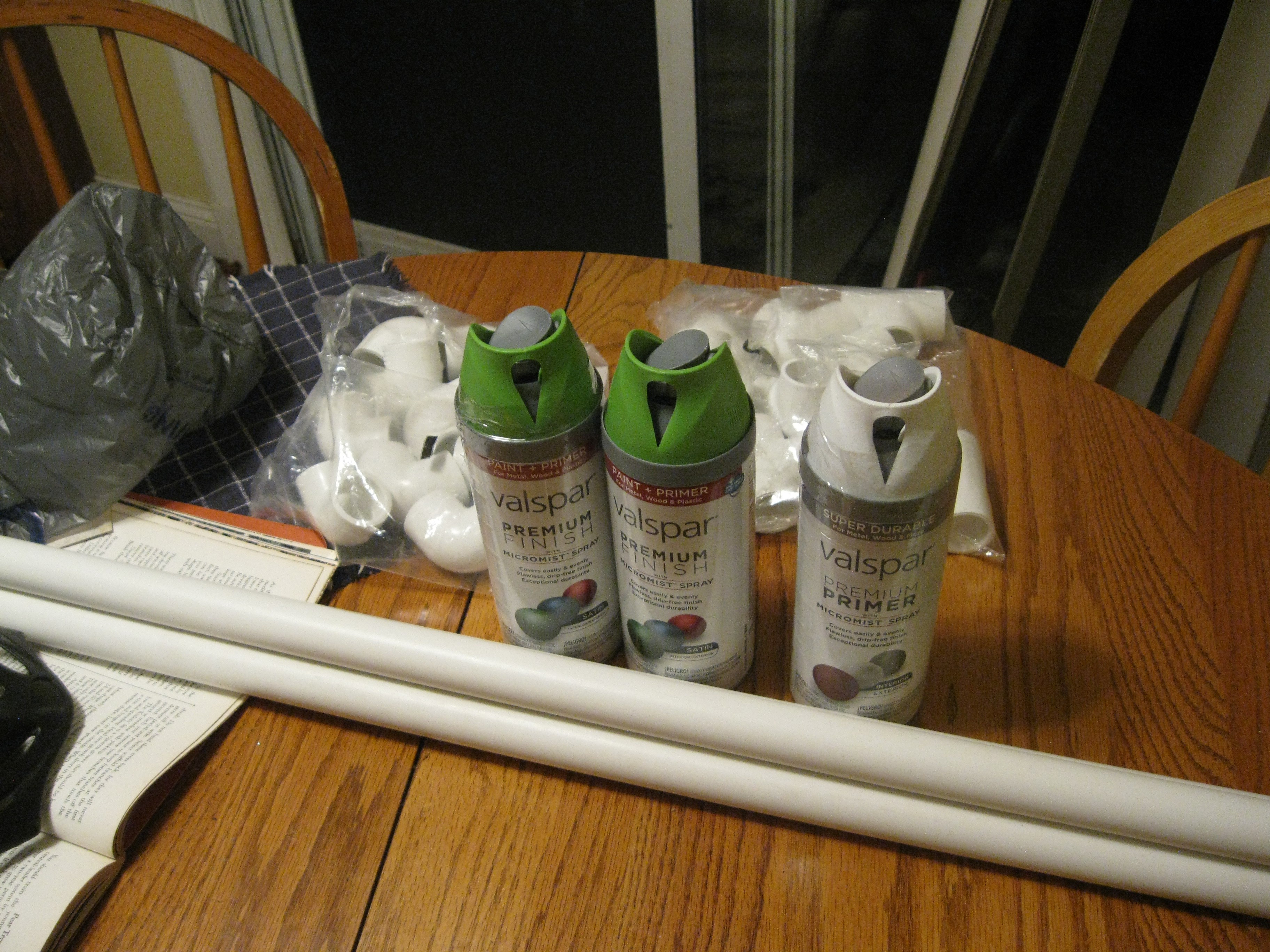
On another note, I went out to the hardware store today and picked up some more supplies for the NFT rig I will be using to deploy and develop HydroPWNics with. I got more PVC pipe for the fitting I have, the missing endcaps for the posts, and some spraypaint for the frame. I got a cool matte green color and some primer so this thing is gonna look pretty. Endcaps not pictured, I couldnt help myself and put them on as soon as I got home.
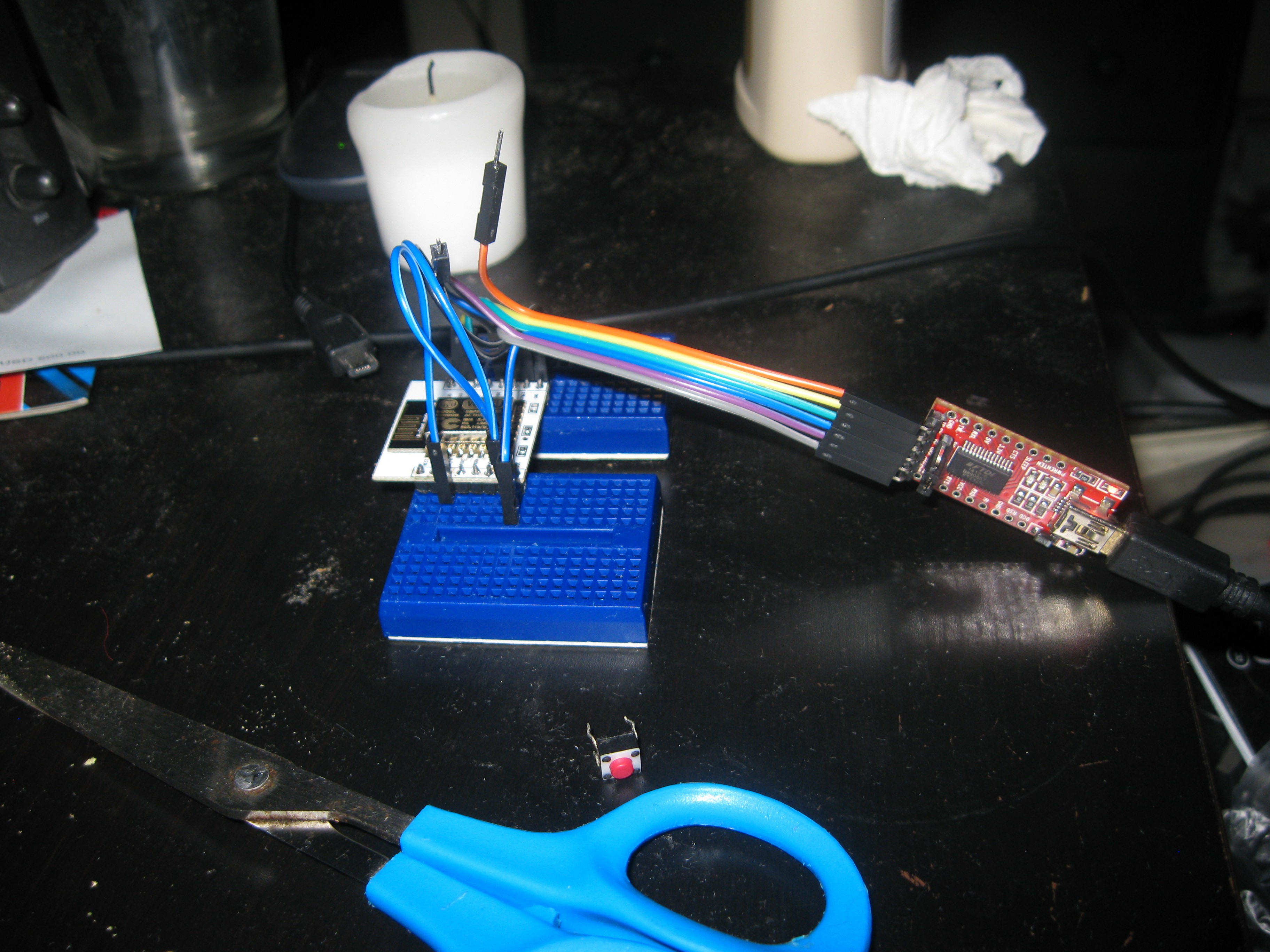
And one more thing, a while back I bought a ton of ESP8266 stuffs on ebay for development and projects. I grabbed up enough ESP-12E modules for populating the Module Hub PCBs but also got a breadboard breakout kit. I soldered it up a while ago and didn't do anything with it. Last night I wired it up with some mini breadboards I had lying around to an FTDI breakout. I just wanted to test the module since i heard counterfeits of this particular one are common. To test the module I loaded example project code from the Arduino IDE with ESP8266 support, I'm happy to say that the module programmed successfully a few times, next step now is to setup the toolchain and learn how to build projects for it that way.
 AVR
AVR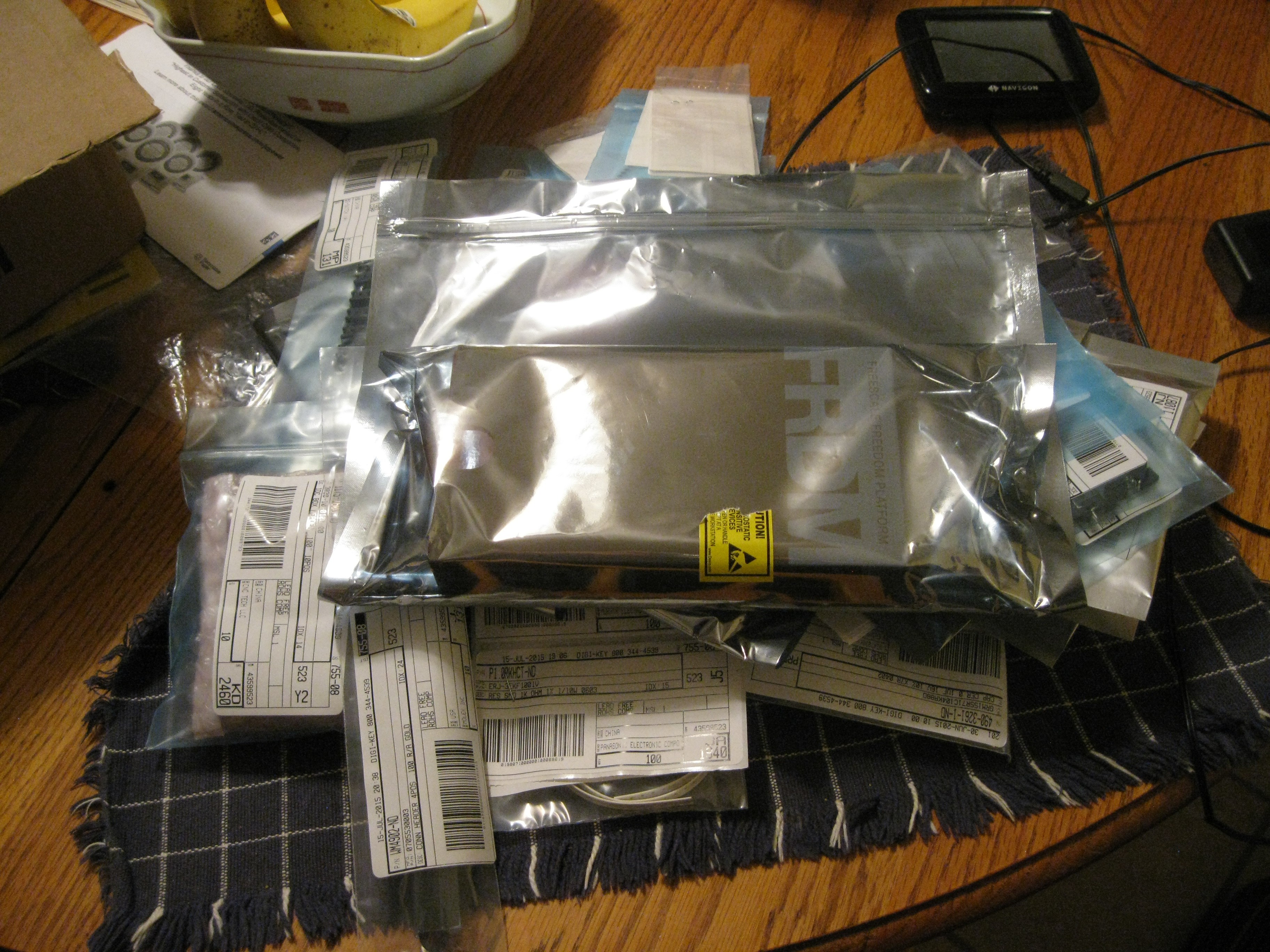
Discussions
Become a Hackaday.io Member
Create an account to leave a comment. Already have an account? Log In.