 Michael O'Toole
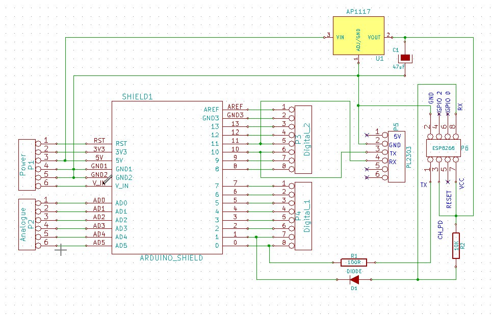
I've made an Arduino Shield for testing.... here's the schematic... (note, I have replaced original post schematic with this simplified version using all thought-hole components)... The PCB layout below is also updated...
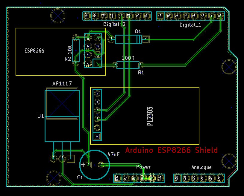
And a very quick PCB Layout...
The original post used 2 BSS138's for level shifting but I may have transposed the TX/RX pins of the ESP8266. This newer layout/schema is what I actually use and has been tested for several months with various ESP's...
Note that the ESP8266 is not suppose to be 5 volt tolerant however, I have tested many and all appear to work perfectly when connected directly to ATMega... If your sketch changes digital pin 0 (RX) to an output, you will need to add level shifting to prevent potential damage to the ESP...
Mike
Discussions
Become a Hackaday.io Member
Create an account to leave a comment. Already have an account? Log In.
Are you sure? yes | no