icstation
Functions
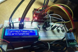
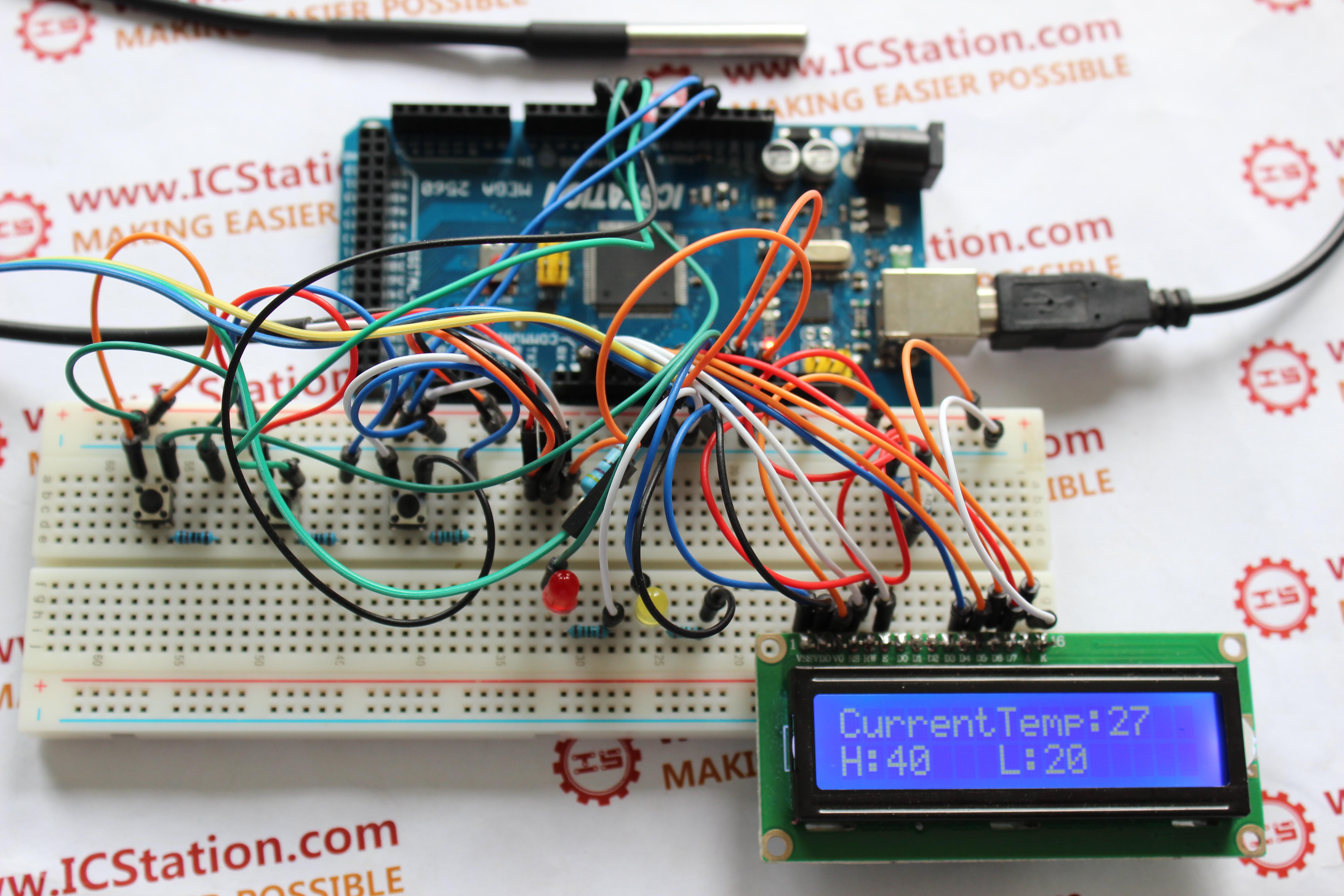
1) When the starting-up hardware initializes, 1602 LCD display module will display the interface which has been setted
2) When the temperature detected by DS18B20 probe is between the minimum and the maximum temperature, buzzer will not give an alarm and LED light won't flash.
3) When the temperature is higher than the maximum or lower than the minimum, buzzer will alarm and LED will flash.
4)Set the maximum and minimum temperature by three buttons.
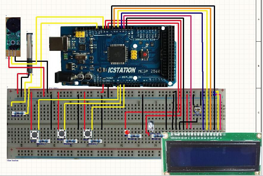
Step 2: The Schematic Diagram

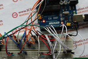
Step 3: Lead to the power supply line and GND
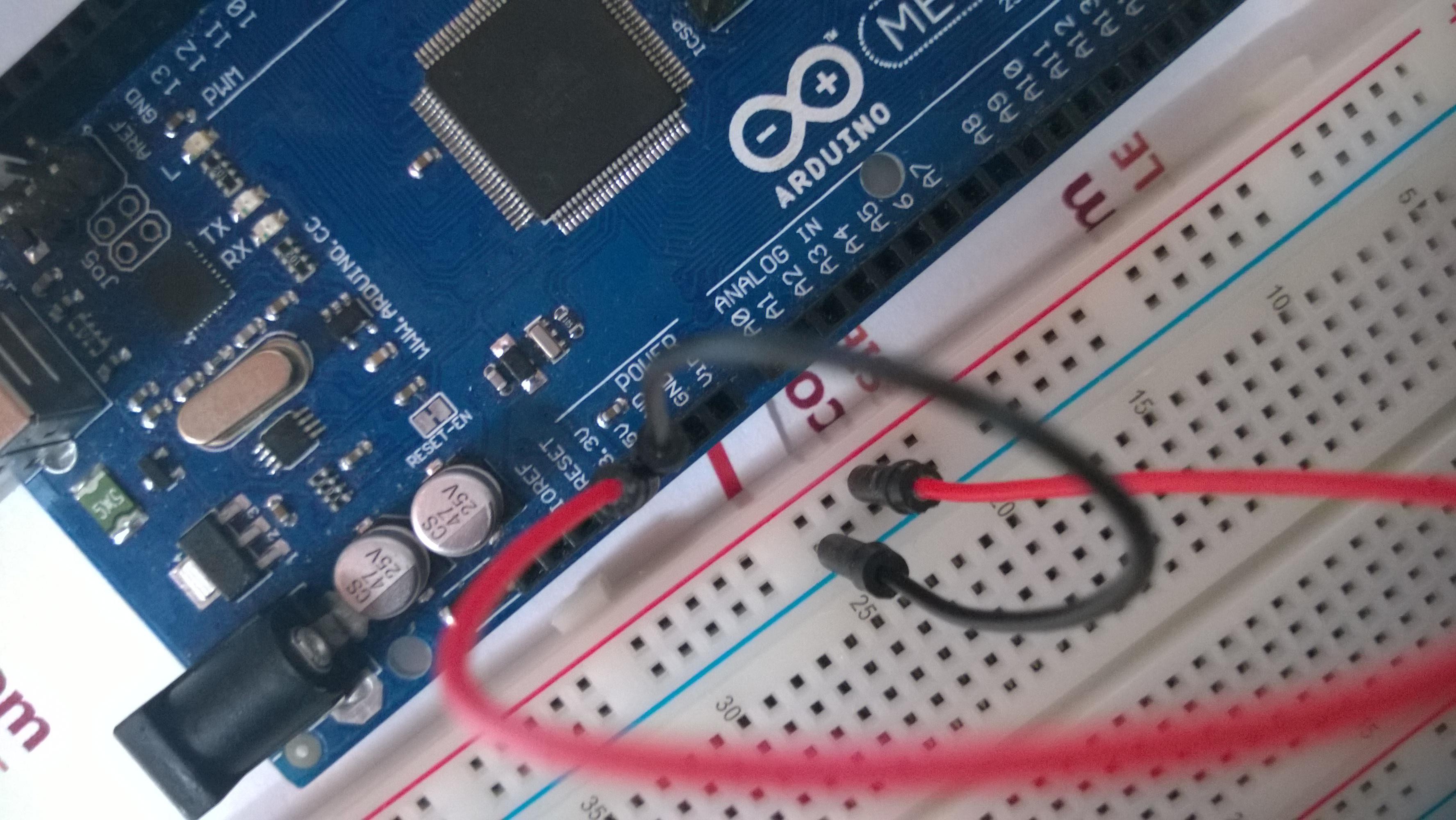
Plug +5V power supply and GND from ICSTATION MEGA development board into the bread board. The red bread wire is used as power line, and black bread wire is used as ground wire.
Step 4: The connection of LCD1602
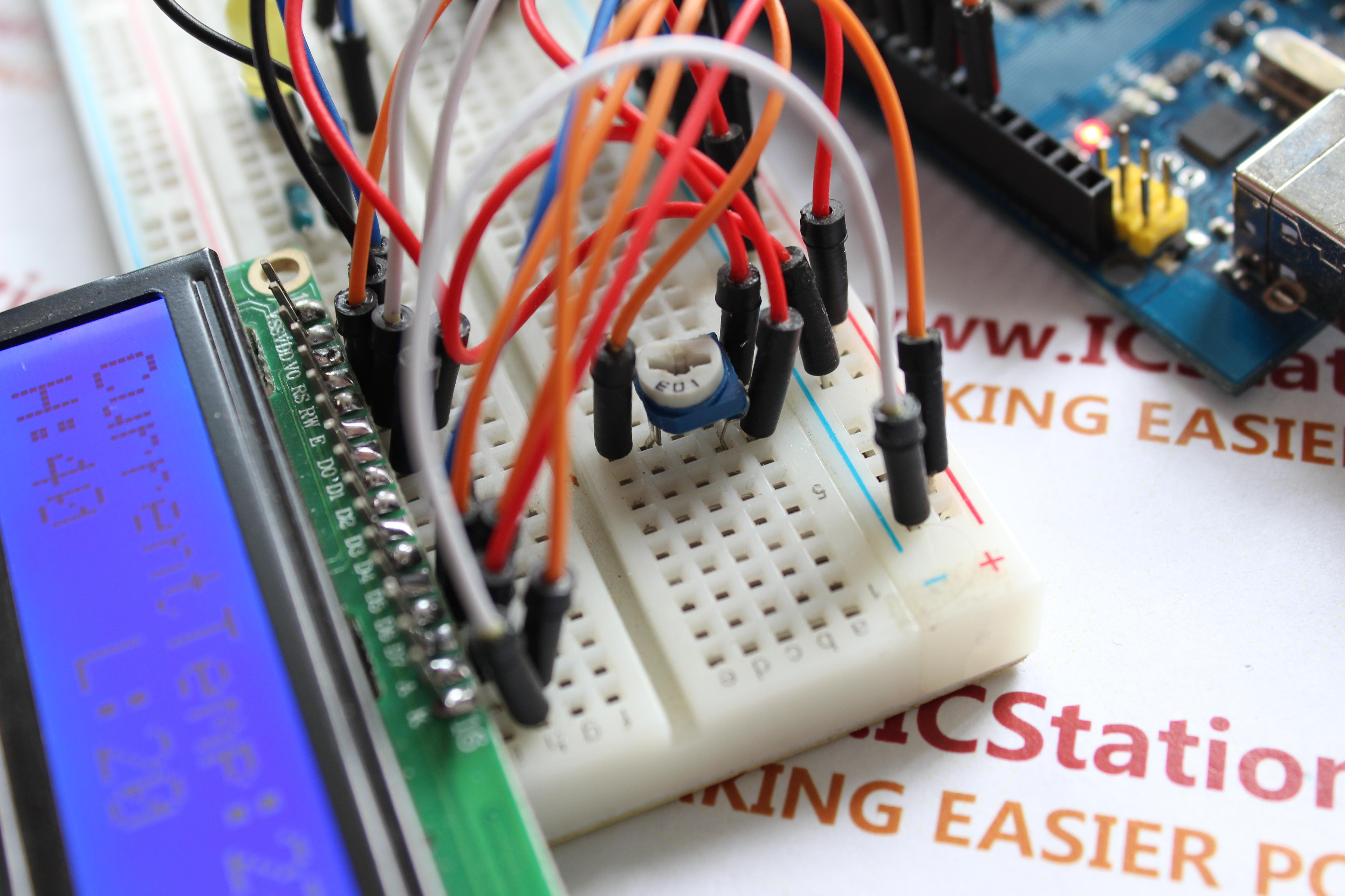
1.Place the 1602 LCD display module on the bread board.
2.According to the schematic diagram, connect the 1602 LCD display module toICSTATION MEGA development board
Step 5: The connection of buzzer module


Connect the pin 1 of buzzer to the anode, pin 3 to the cathode, pin 2 of the buzzer to pin 10 of ICSTATION MEGA development board
Step 6: Place the LED
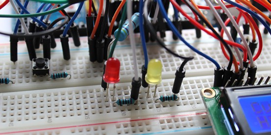
Step 7: The connection of switches and limited-current resistance
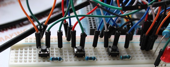
1. Place the switches and 1K current-limiting resistance
2.Connect Pin 1 of the three switches to +5V, Pin 3 to GND. And connect Pin2 of add switch to A0,Pin2 of points decrease switch to A1, Pin2 of selector switch to A2.
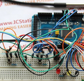
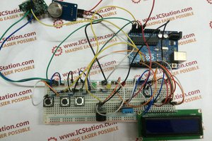
Step 8: The demo diagram of experiment effect
Step 9: Video
http://youtu.be/JP0c381nSAg

 opeRaptor