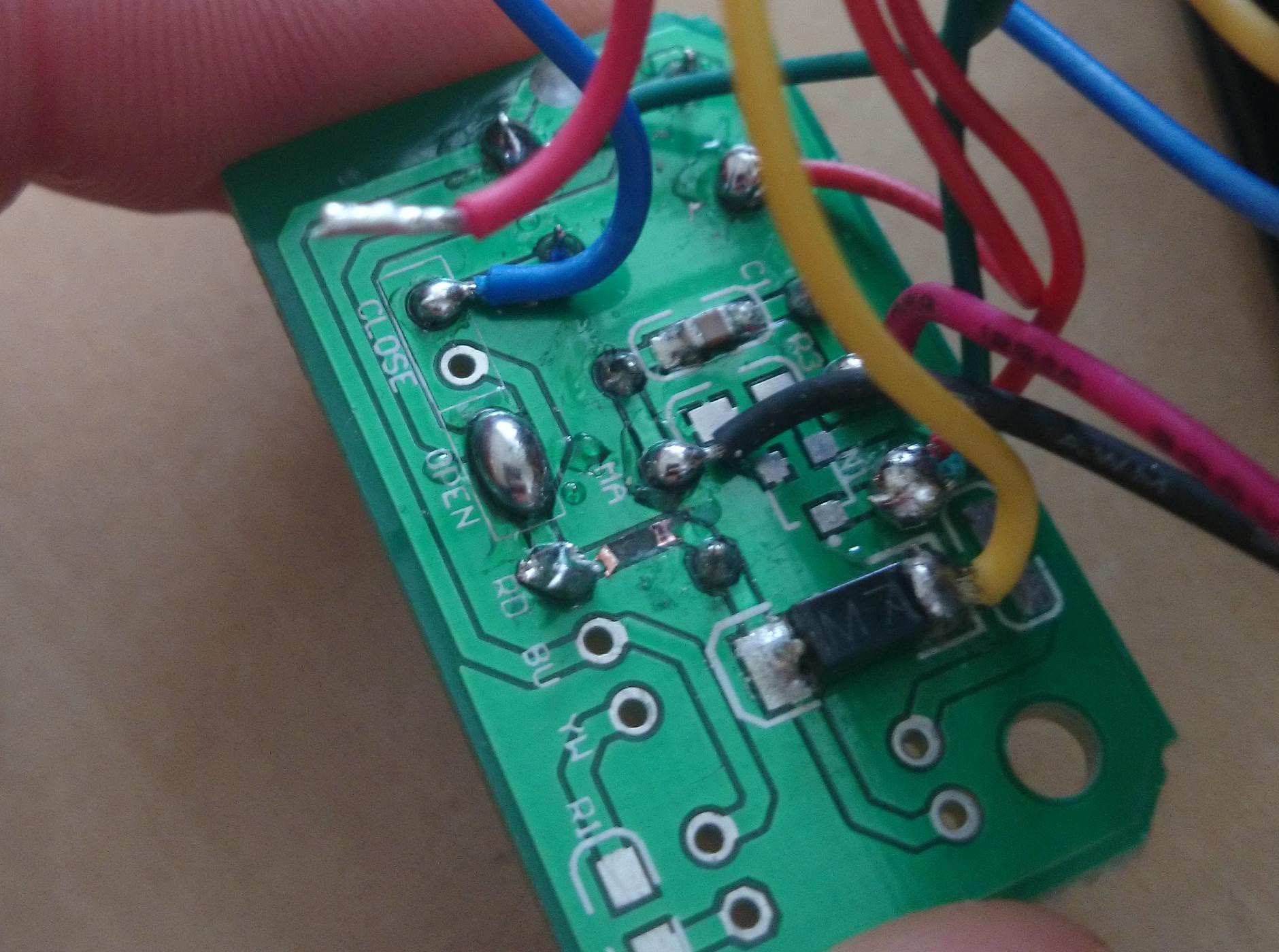
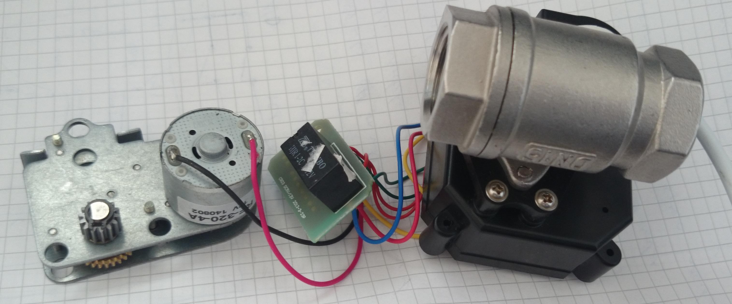
For some reason, my valve never worked. I disassembled it and found it would only close, but not open anymore. I found a blown trace on the PCB which I repaired, but it's still short-circuited somewhere. I believe either the reverse-voltage protection diode or the relay coil are blown and now permanently conducting. Both are easy fixes, but still very annoying.
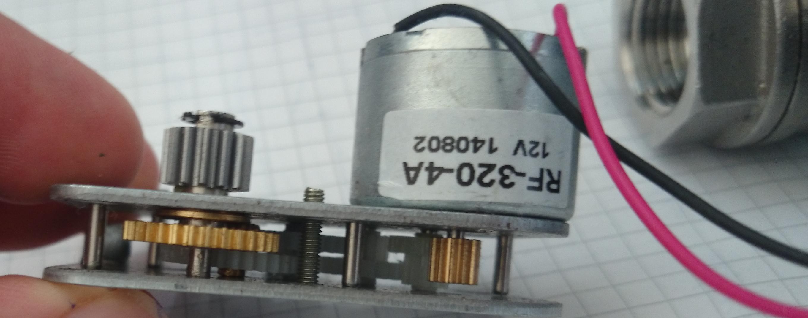
The CR-02 valve is actually nicely built and probably good value for your money. The PCB is sufficiently well made and the gear box looks solid. Of course, some gears are plastic although it's advertised as a brass gear box. I just wish they had added a proper fuse to the PCB instead of just letting some traces burn out.
Edit: I just did some further test and it is indeed the diode that's burnt out and now conducts in both directions. I know that diodes are used in this way to protect against wrong polarity. In this case, all current flows through the diode and back to the battery. The key ingredient here is a fuse which prevents further damage to the circuit. The manufacturer didn't include that fuse, so the PCB trace blew up. I'm reasonably sure I did not reverse the polarity, but you can never know afterwards. It's also possible that the diode is simply supposed to act as a suppressor diode for the motor.
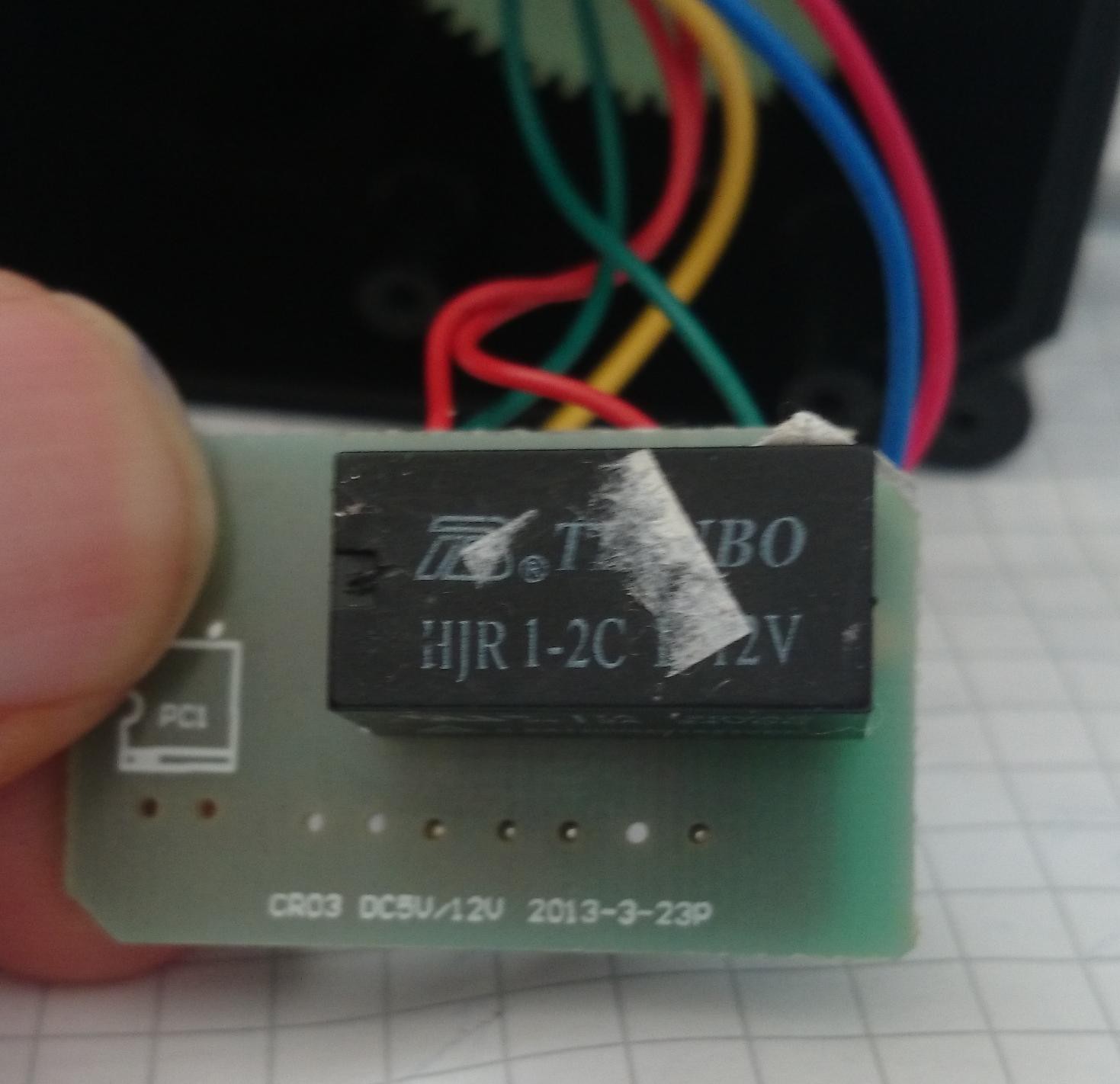
Edit2: It's likely a suppressor diode for the relay coil.
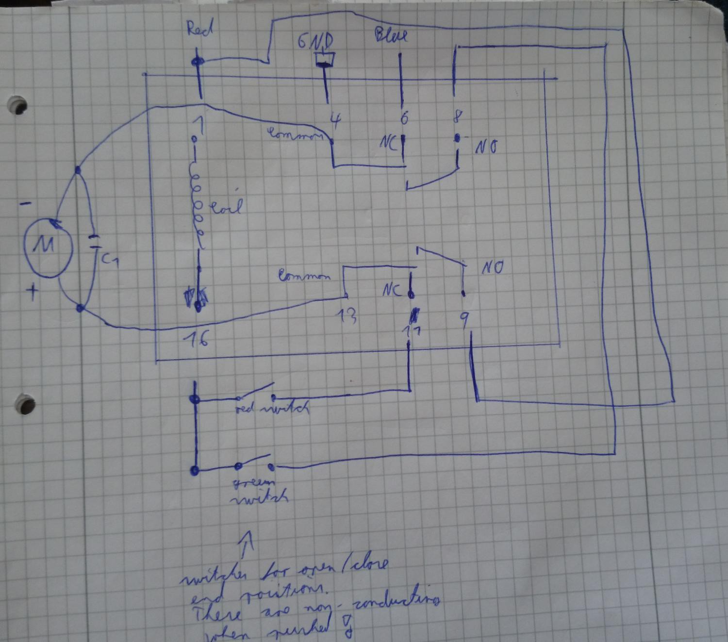
Anyways, I have (badly) drawn up a schematic which will hopefully help other netizens.
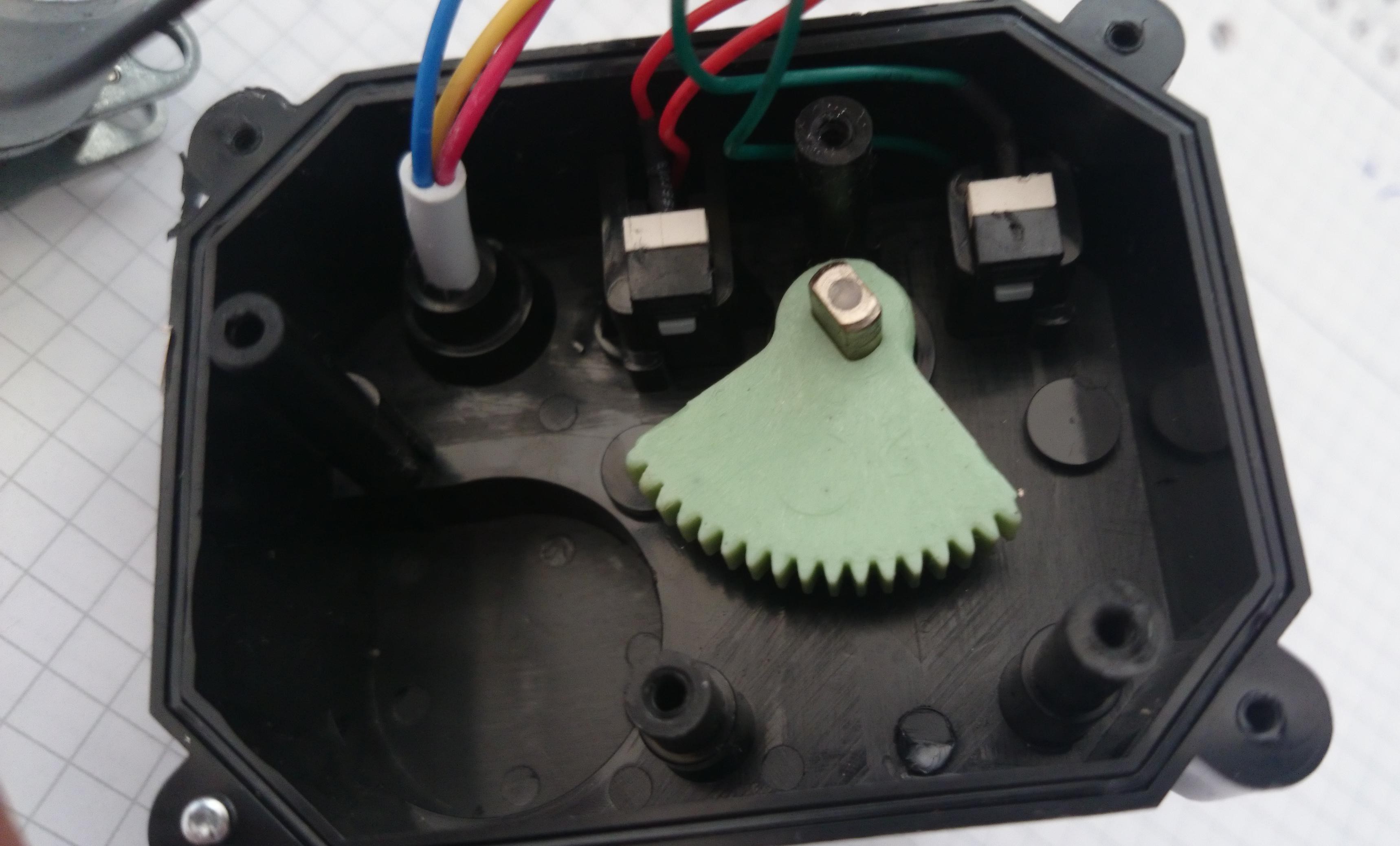
The blue (CLOSE) wire is connected to the NC pin of the relay. This is kind of the default action for the valve. The red wire (OPEN) fires up the relay coil which changes the turn direction of the motor. There are two end switches (green wires and red wires) which disconnect GND once the respective end range of motion has been reached. These switches are conductive by default and turn off the motor when press.
For your amusement, here is the burnt out trace:
 Michael Haas
Discussions
Become a Hackaday.io Member
Create an account to leave a comment. Already have an account? Log In.