-
Connect the Chirp to your LaunchPad
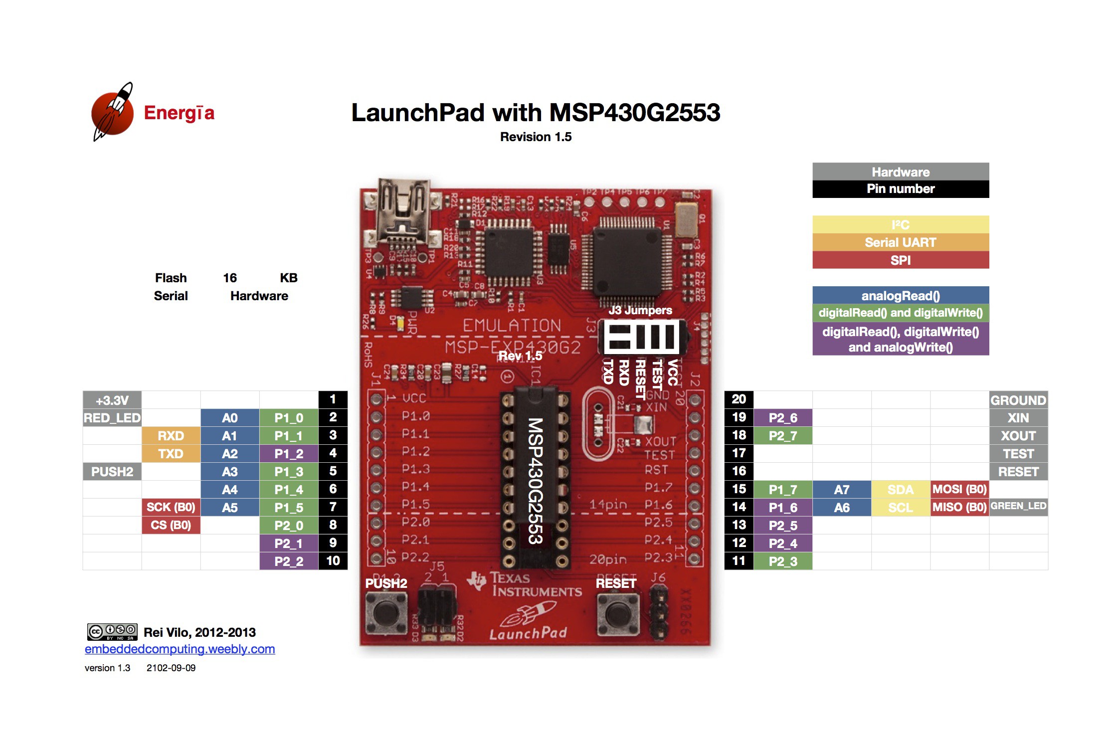
10/18/2014 at 18:41 • 5 commentsNow that you've hopefully ordered and received your chirp! sensor ;), it's time to connect it to your LaunchPad. The basic process is very simple, as the Launchpad acts the I2C master and the chirp! is an I2C slave at address 0x20. So let's look at the pins on the LaunchPad:
![]()
The yellow highlight marks the I2C pins SDA and SCL at P1_7 and P1_6. What threw me off here is that the pins on the chirp! also serve as an ISP header - if you want to re-program the sensor, you can do so. The pin names printed on the PCB align with the names of the SPI pins, however. So I initially connected the SPI SCK on P1_5 to the chirp!, which was completely wrong. After all, I only need SCK, SDA, VCC and GND. So here is the final mapping I derived from the chirp! documentation.
- Pin 15 (P1_7) to "pin 4 - MOSI / SDA – I2C data"
- Pin 14 (P1_6) to "pin 3 - SCK / SCL – I2C clock"
- Pin 1 (VCC) to VCC
- Pin 20 (GND) to GND
Then I fired up the latest and greatest Energia, loaded the example sketch from the chirp! documentation and got.. nothing. Tripple-check everything, still nothing. I search around and find some hints that the I2C clock needs to be reduced in some cases. Basically, an I2C slave can reduce the communication speed in what is called "I2C clock stretching" and that's broken on some devices. Fascinating stuff, go read about it.
I finally found a way to adjust the I2C clock by.. reading the documentation. If you ever despair that you can't find the right register, then be warned: some msp430s use the "USI" system for I2C, some use "USCI". Make sure to use the right registers or it won't compile...
Of course, it still didn't work. I posted over at the great 43oh.com forums where I was told I need some pull-up resistors. What? The chirp! documentation does not mention anything beyond "hook it up via I2C and use this pin mapping". The author probably assumes everyone knows about pull-up resistors, and that assumption probably is correct.
So, pull-up resistors: connect a 10k resistor to VCC and connect it between the MCU pin and the I2C slave pin. Do this for both the SDA and I2C pin. Then, the Arduino example magically starts working at the default bus speed.
The reason is that the bus should be logic high, i.e. at 3.3V, by default. That's why we connect the bus to VCC. Because we don't want to allow an unlimited current flow, we put in a 10k resistor. Otherwise, the magic smoke will escape. Now the line is logic high, but only very limited current is available. If the devices want to communicate, they pull the bus low by directing the current to GND. At least, this is my _very_ basic understanding of the issue. Remember, I'm a natural language/software guy, not an electronics engineer.
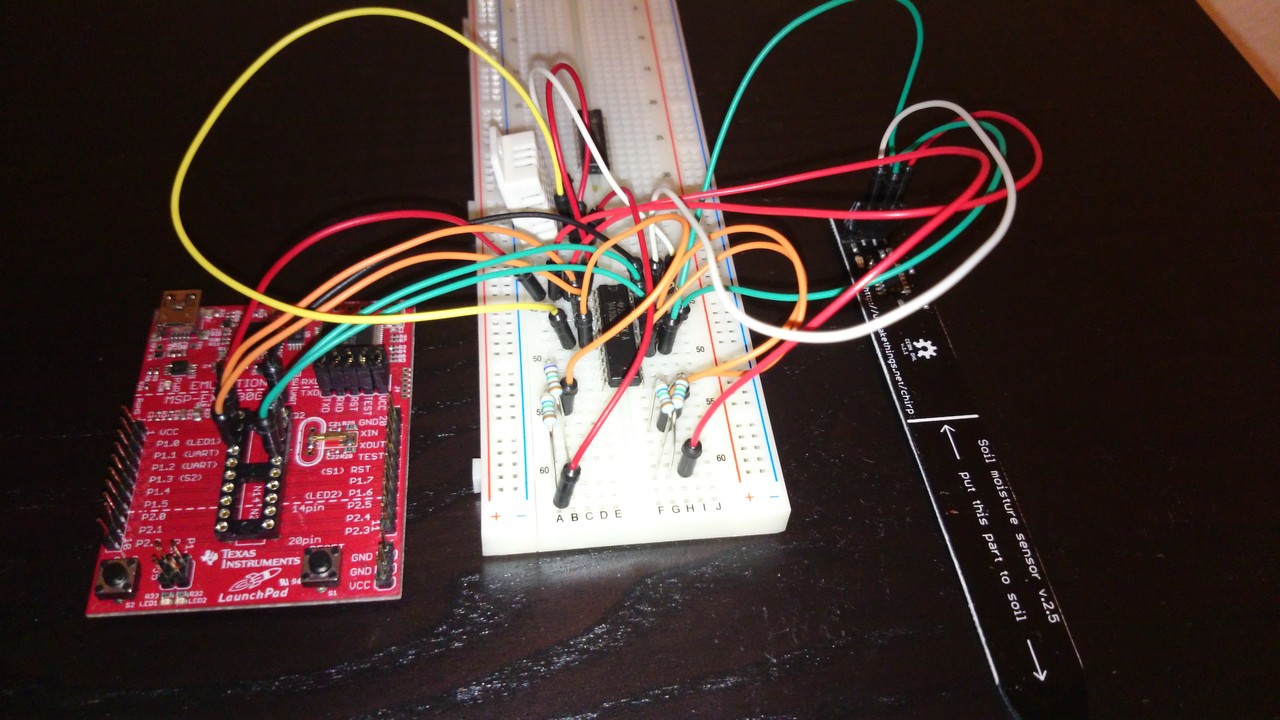
Here's the slightly overexposed result. There is a second set of resistors and some wires for the DHT22, which I will hopefully get working soon.
-
On soil moisture sensors...
10/18/2014 at 18:04 • 0 commentsToo dry and your plants will wilt. Too wet, and the roots will rot. So you're going to need a moisture sensor.
The standard method in the hobbyist community seems to be a resistive sensor. You take two electrodes, e.g. two nails, put them in the dirt and measure the resistance between the electrodes. This approach has several problems. First, the resistance measurement is temperature dependent and soil temperature is not very stable, especially outside. So you to measure the temperature and correct for that. Second, electrolysis will happen and one electrode will corrode. Basically, you build a machine that generates random resistance readings and rust.
No, it's not that bad, of course. Resistive sensors have been successfully used by many people. For example, the Cheap Vegetable Gardener described such a sensor five years ago. If you look around, you can even find some ready-made gold-plated electrodes for the task on ebay. Gardenbot also describes a setup which avoids electrolysis.
A capacitive method is much more elegant. You basically make a capacitor where the soil becomes the dieletric medium. If the soil becomes wet, the dielectric properties of the water dominate and the capacity of the capacitor increases. This method is much more reliable, although it still requires some calibration. Micah J. Waldstein has a some nice blog posts on his own "grow with arduino" experience where he works with capacitive sensing.
Now, where can you get one of these capacitive guys? Miceuz from the Wemakethings.net hacker space in Lithuania designed a capacitive soil moisture sensor. He calls it "chirp!" and he even has a detailed writeup on the design (1, 2). The best thing.. no, wait, the best three things: both hardware and software are open source and it's easily hooked up to a micro controller via I2C. Actually, the best thing is he sells these pre-built on tindie for a great price. There is a standalone version which goes "chirp!" and a sensor-only build which acts as an I2C slave.
That's it! Note that I did provide some additional links on different sensor types and implementations. During my research, I found lots of other nice sensor projects. So, if you need even more information, just hop over to your favourite search engine.
Magnificent Moisture Management
I've got a balcony, tomatoes and a micro controller
 Michael Haas
