 Greg Duckworth
By utilising the 2 Axis mill and purchasing some 5mm * 100mm * 1m 6068 Aluminium, I was able to start milling motor mounts, bearing holders and mounting plates for the Z axis. These were taken from one of the previously mentioned websites (All construction documents will be added when the conversion is complete).
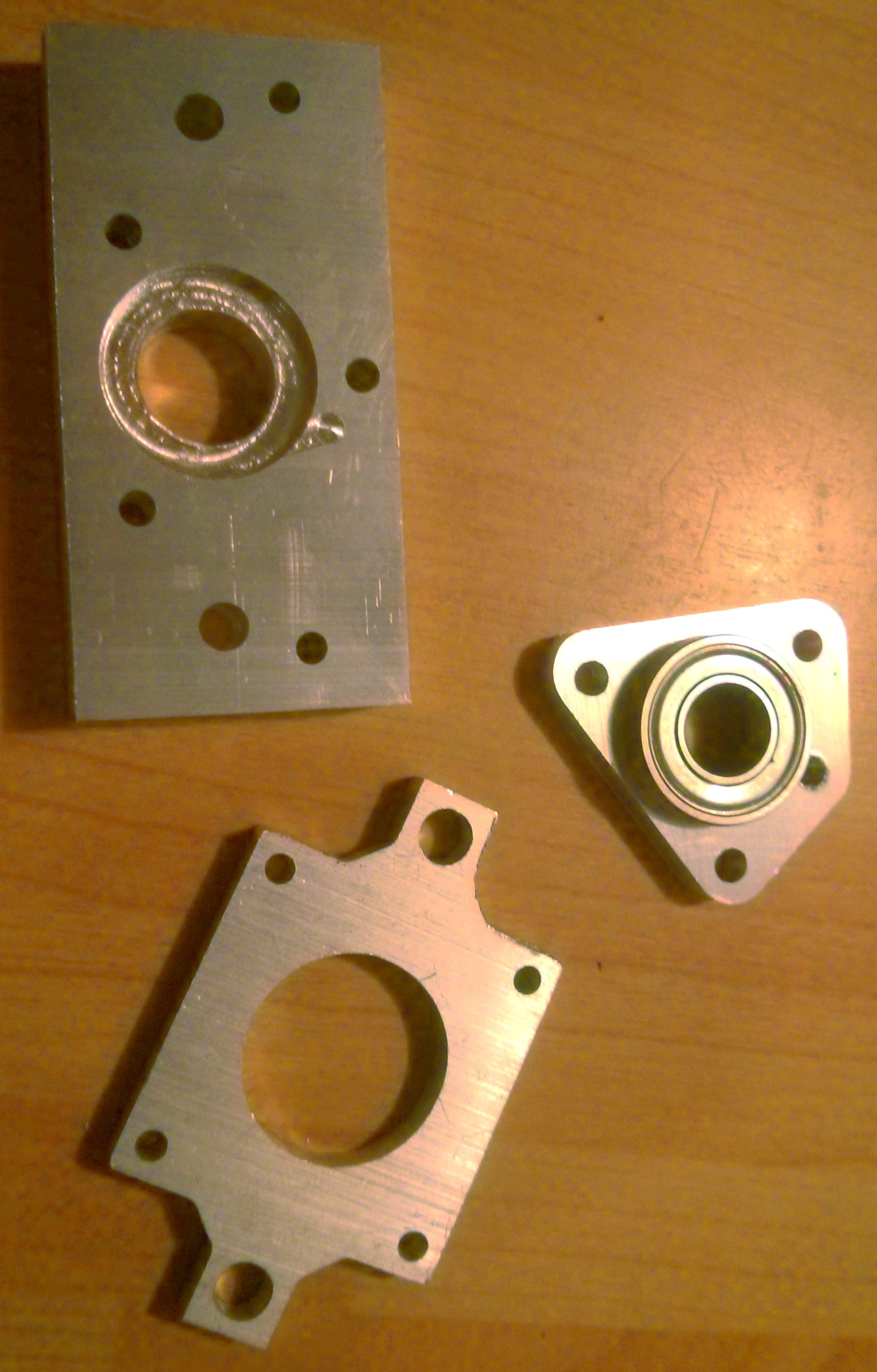
The milled parts required for the Z Axis conversion. There are a few cosmetic issues but nothing serious. Every hole was machined with a separate milling operation which took a long time. This was to avoid any rapid moves while the Z axis is manually controlled. Many of the holes are to be tapped M4 or M6.
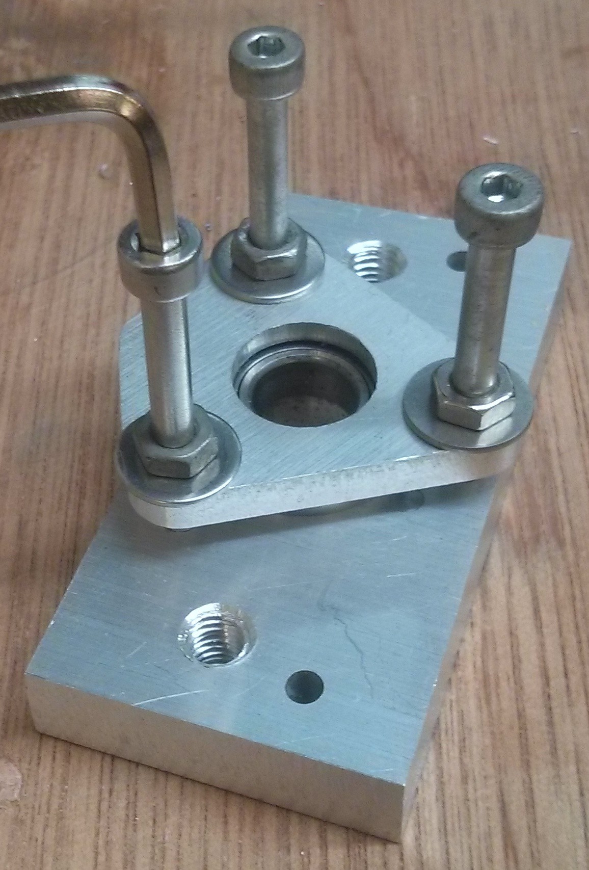
The parts were assembled (the bolts in this picture were replaced with shorter cap head bolts after the bearing retainer was seated. The previous coupling was made of ABS plastic but I wanted to remove the handwheels from the build. I made a brass coupling on grandads lathe. This was the only part that required a lathe in this build but there may be other ways of doing this.
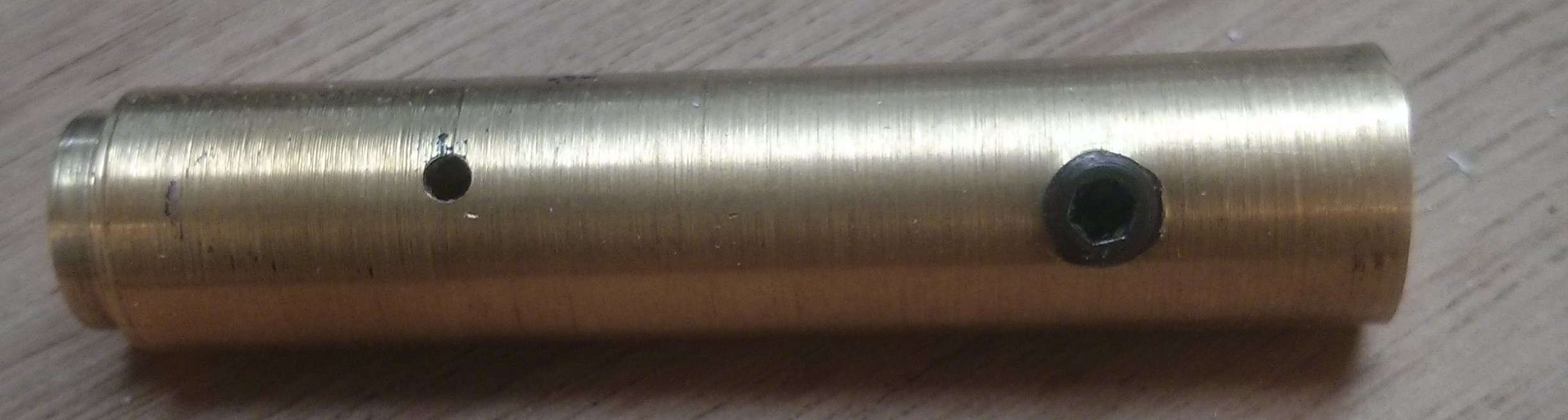
The shoulder was turned to accurately fit in the bearing so as to reduce runout. On larger machines it is inadvisable to directly couple two shafts end to end. In this case the misalignment will be taken up by the flexibility in the threaded rod. The small hole is for the spring pin which holds the leadscrew.
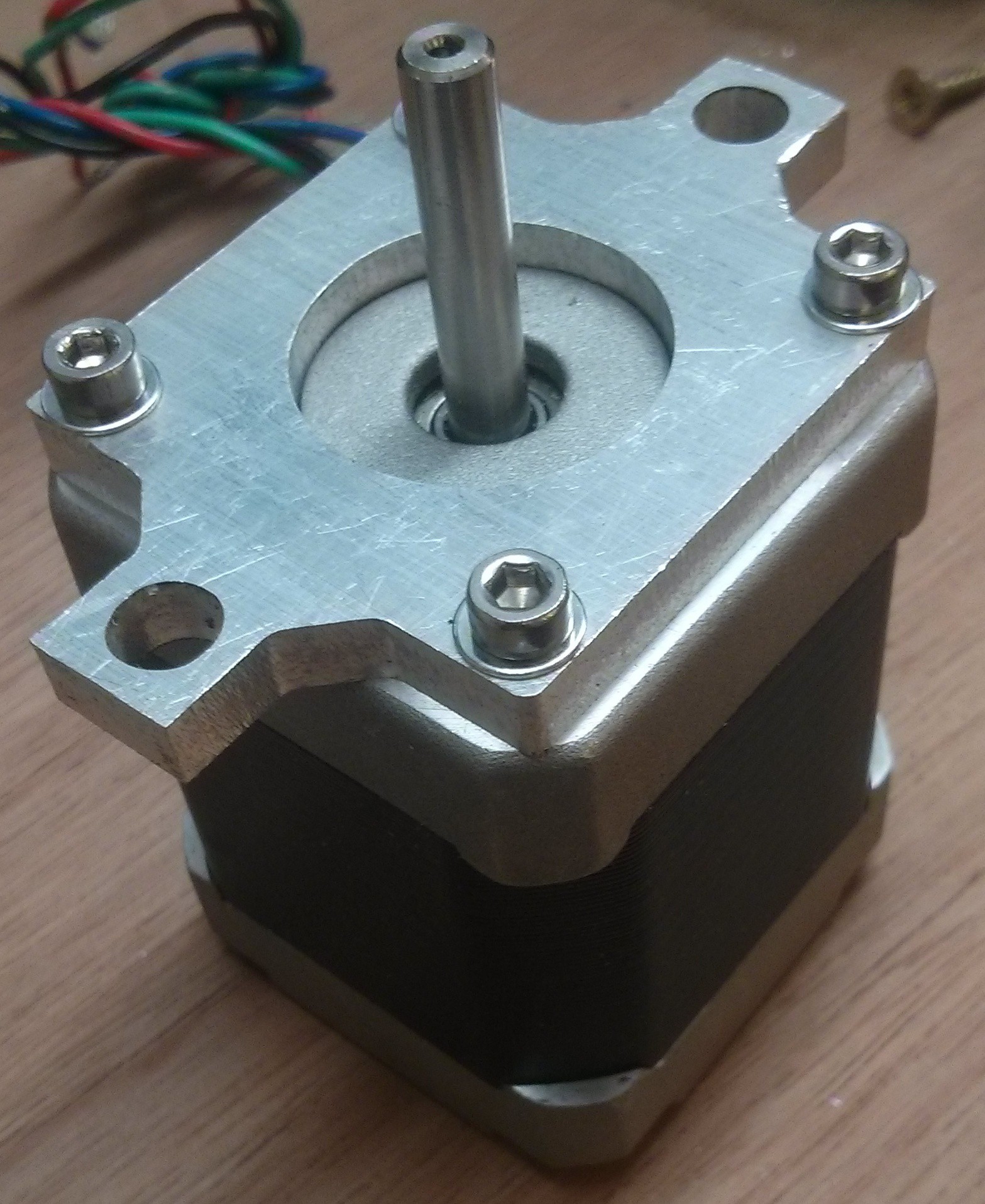
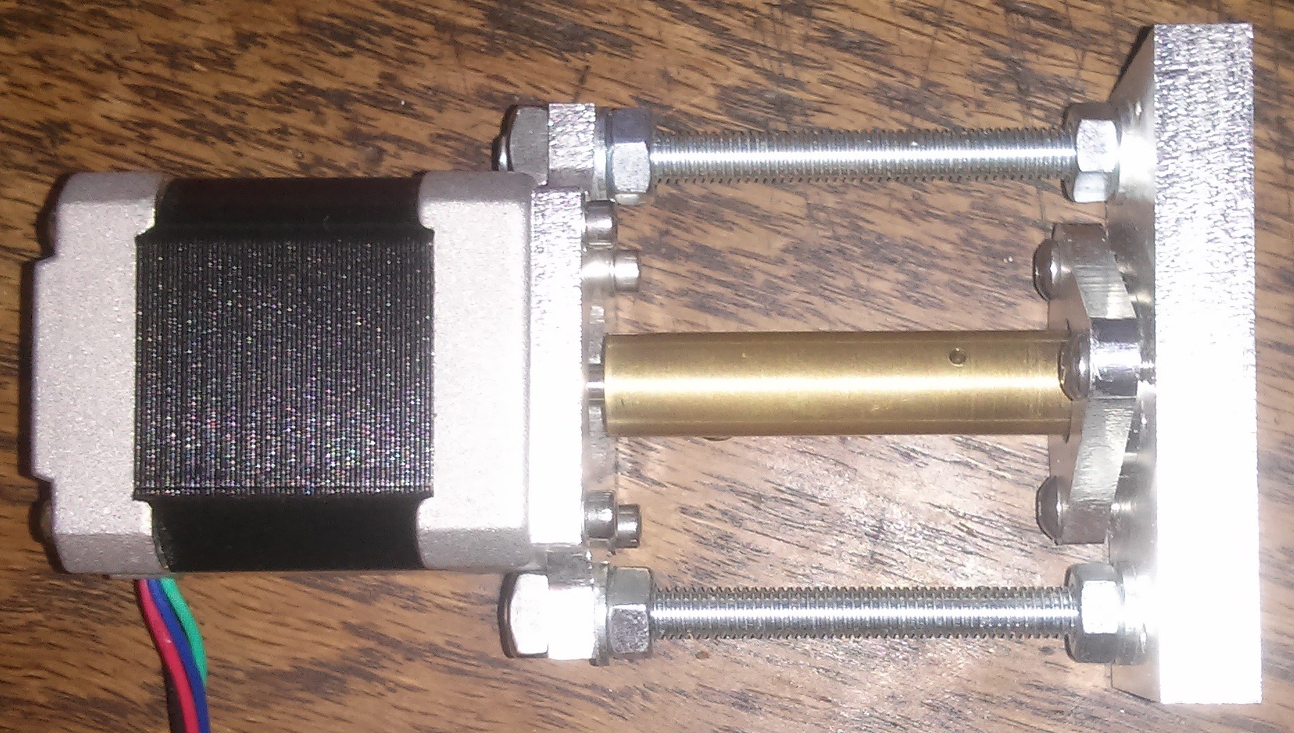
Shows the motor mount with the shortened bolts. The washers helped reduce the marking of the aluminium and are very recommended.
This is the finished Z Axis, only two unfilled holes which are for mounting the Z to the top of the milling machine.
Discussions
Become a Hackaday.io Member
Create an account to leave a comment. Already have an account? Log In.