 Adam Fabio
I designed my PCB in my favorite software - Diptrace. The motor footprint from switec's datasheet was missing a few key dimensions. It took a bit of measuring with a caliper and calculating hole sizes, but I was able to get all the dimensions correct on the first rev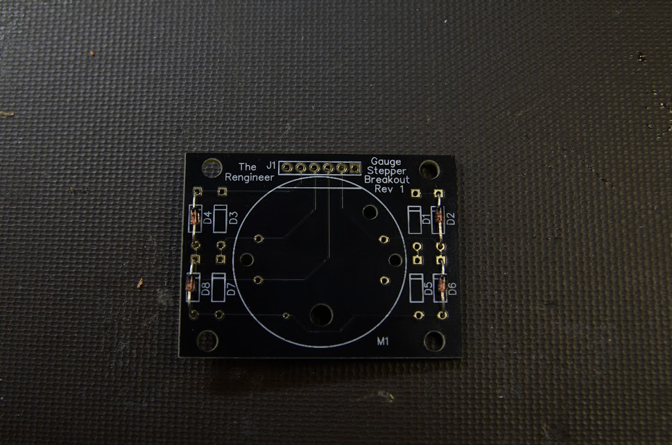
I also installed some flyback diodes. Each time the motor's coil is switched on and off, there is an inductive spike created. 8 diodes direct these spikes to the power rails, protecting the output pins of the microcontroller driving the motor. I added a standard .100 header, some all important mounting holes, and sent the design off to OSH park.
Discussions
Become a Hackaday.io Member
Create an account to leave a comment. Already have an account? Log In.
Are you sure? yes | no