The "final" final PCBs arrived today, so I proceeded to do a quick assembly log.
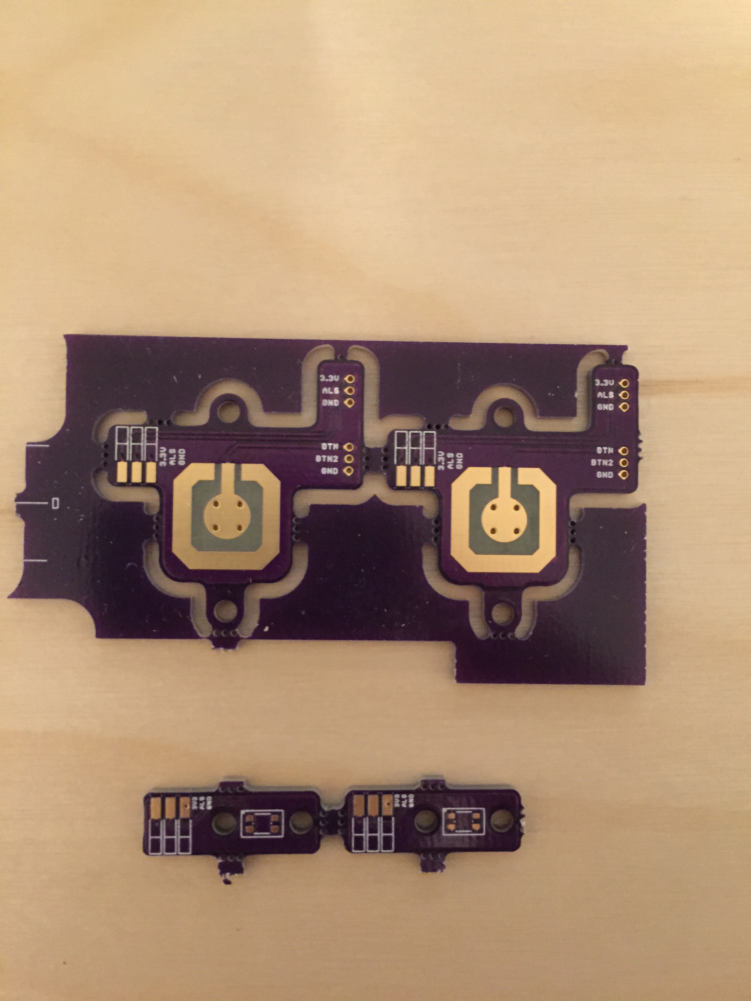 PCBs for the button and ALS. Apparently the button was too complex for OSHPark to de-panel properly. No big deal.
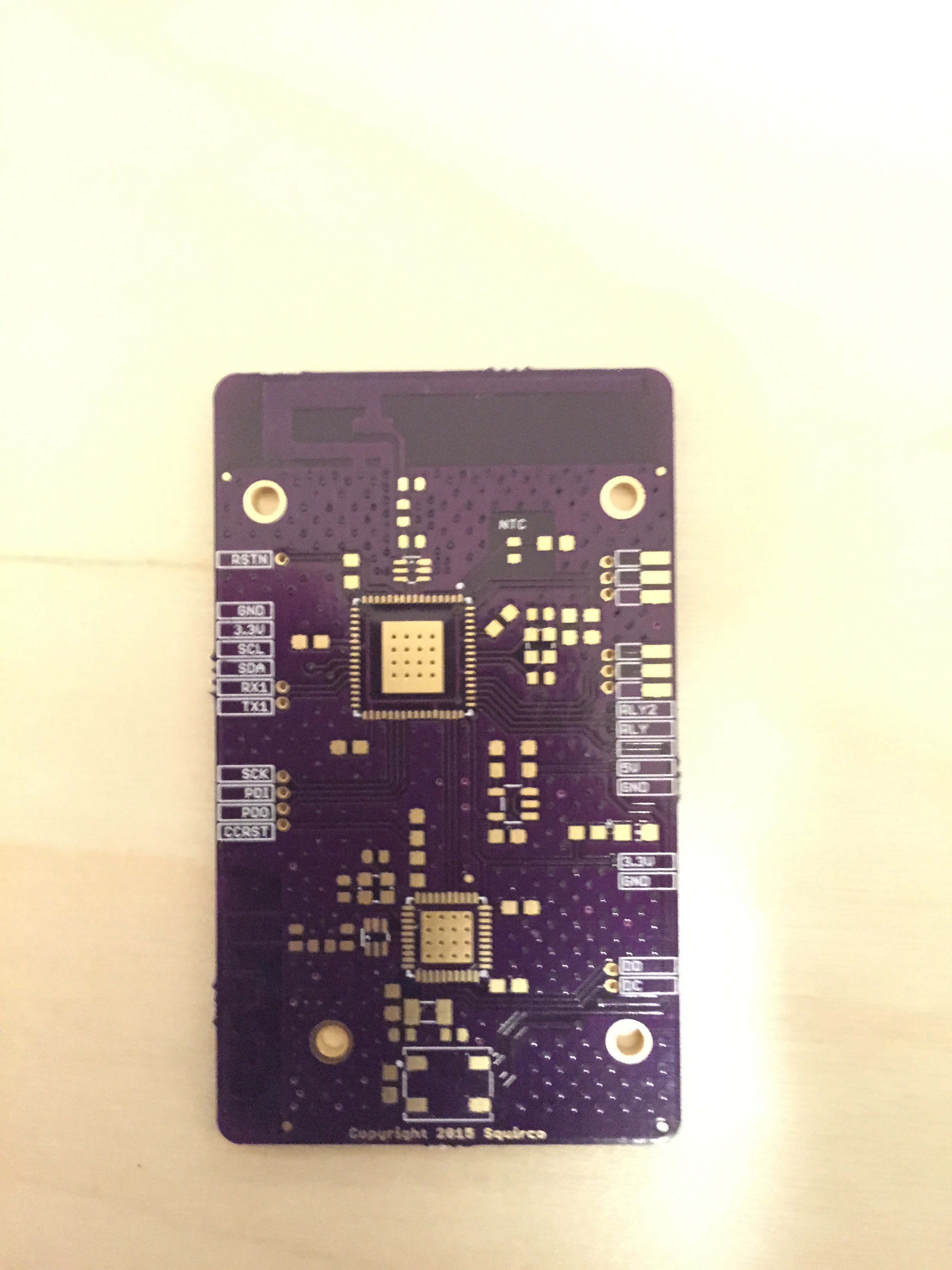
Un-assembled Logic PCB.
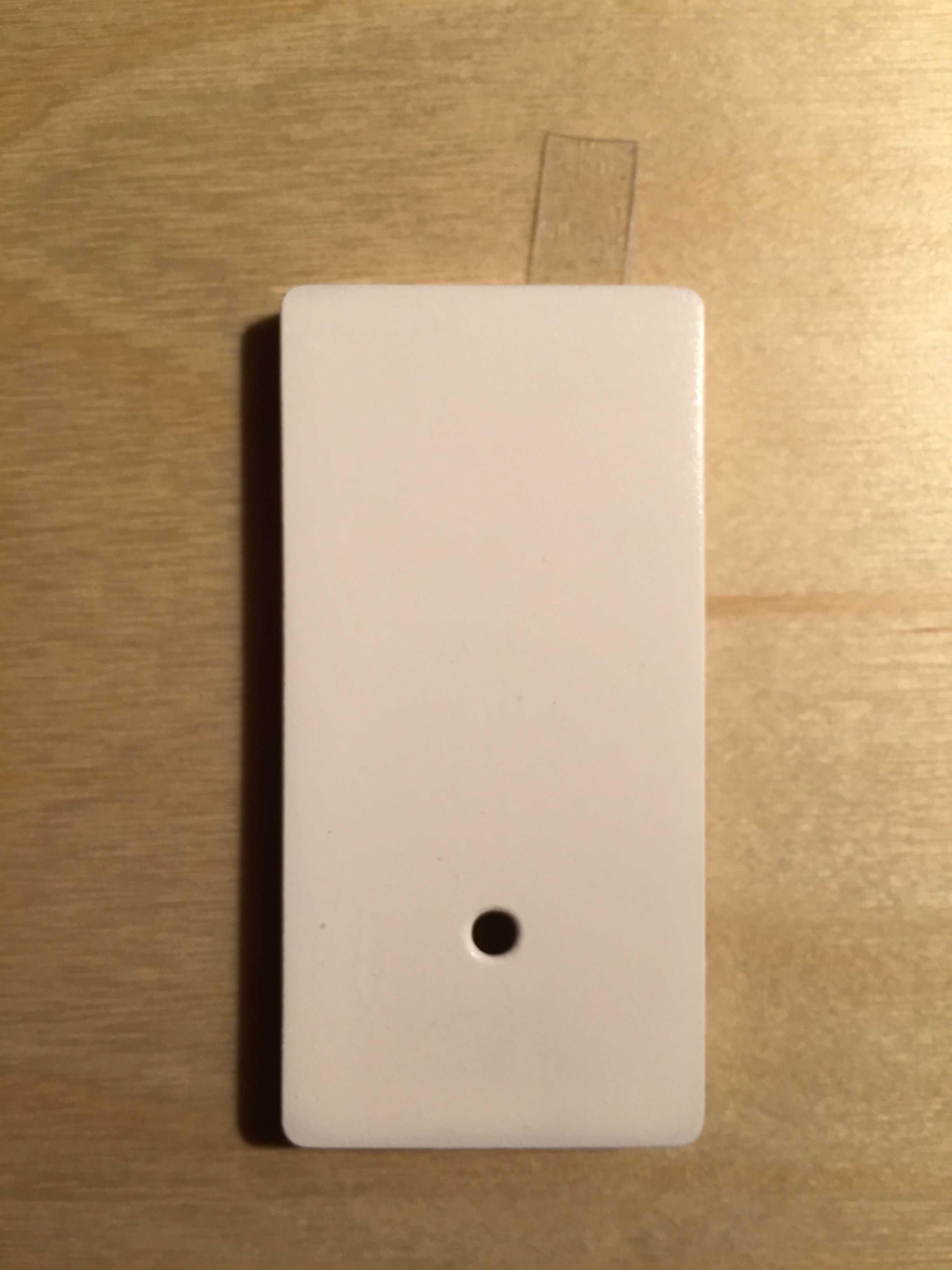
Front of the button. The button was ordered at Sculpteo and spray painted glossy white.
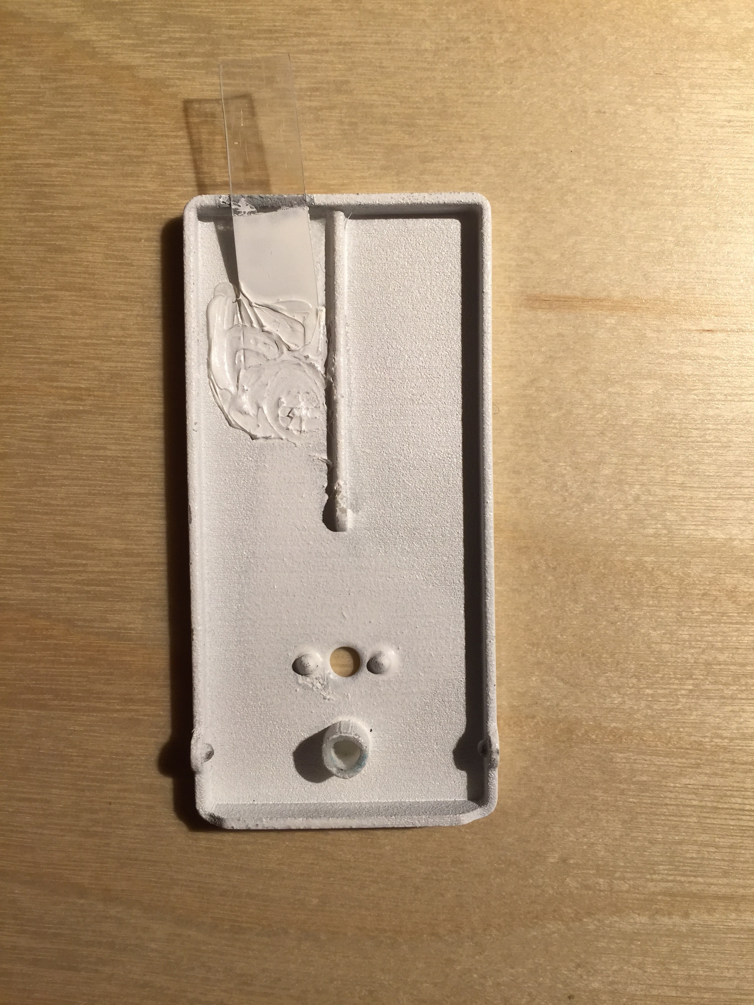
Back of the button. A strip of blister pack plastic was added to act as a spring, as well as keep the button top from coming out of the face plate too far
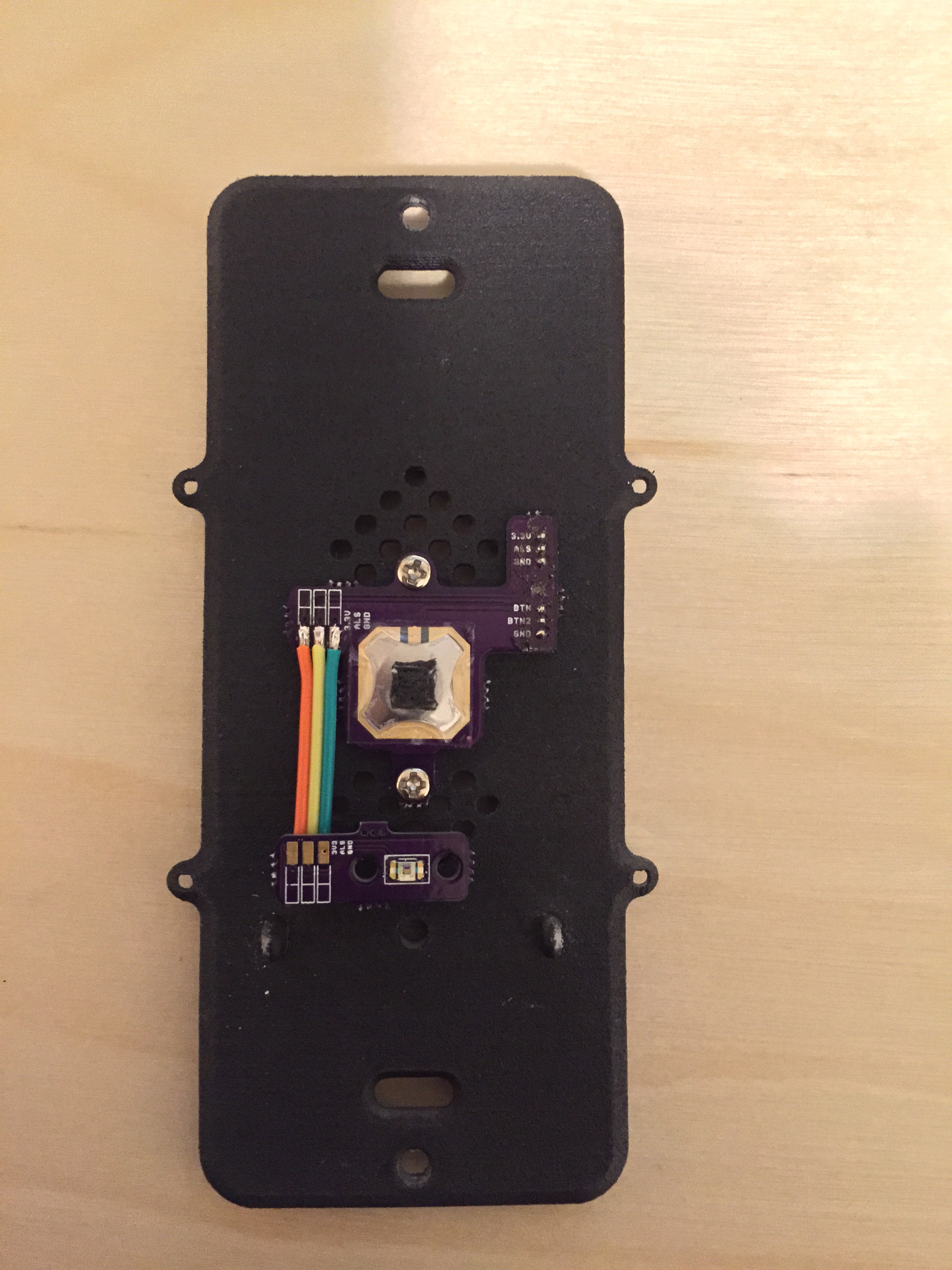
The button test mounted onto the mounting plate. A piece of black foam is super glued to the button for a tighter fit and more crisp response.
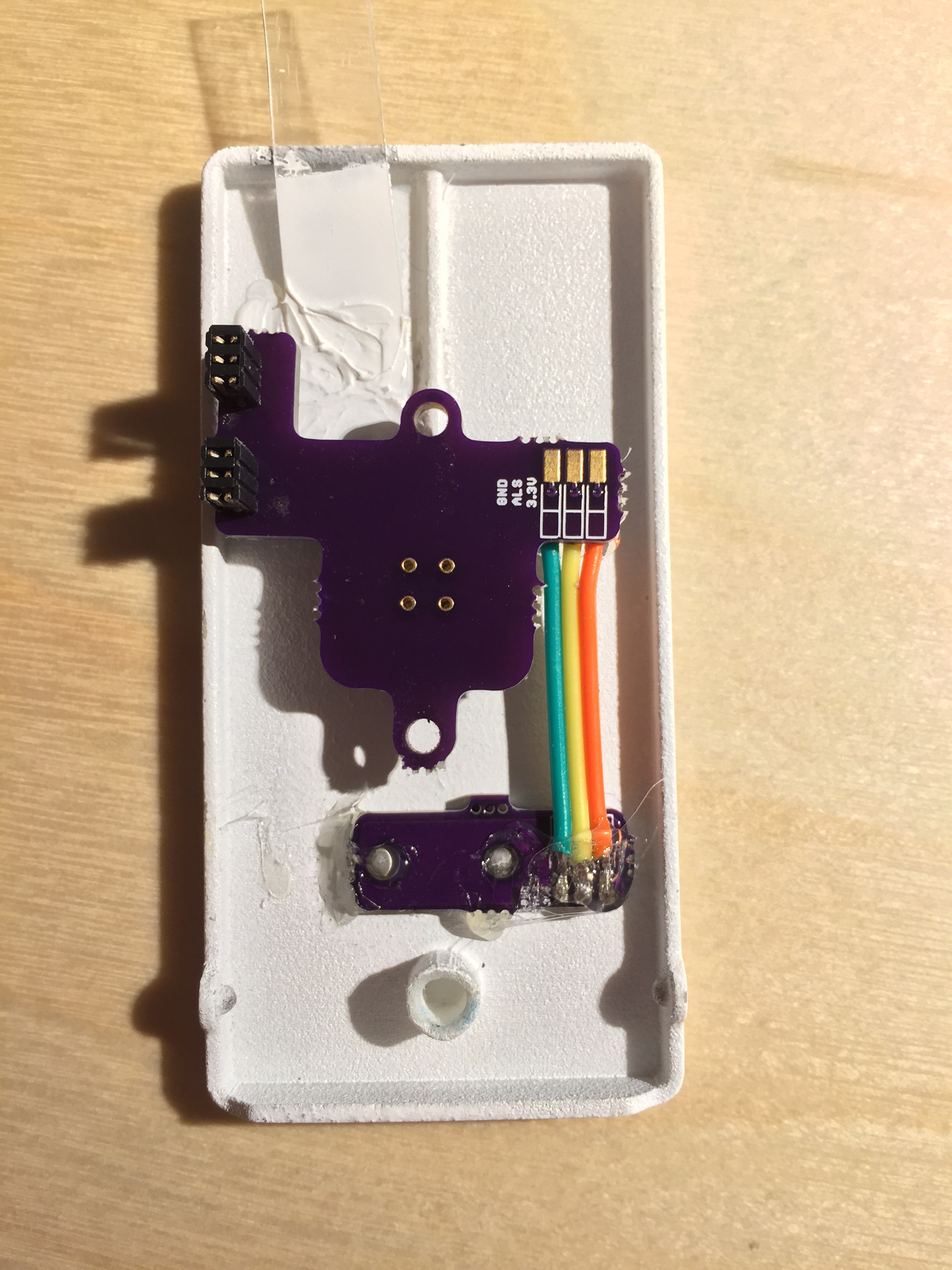
The button/ALS assembly hot glued to the button. The solder terminals are also covered in hot glue to prevent them from snapping.
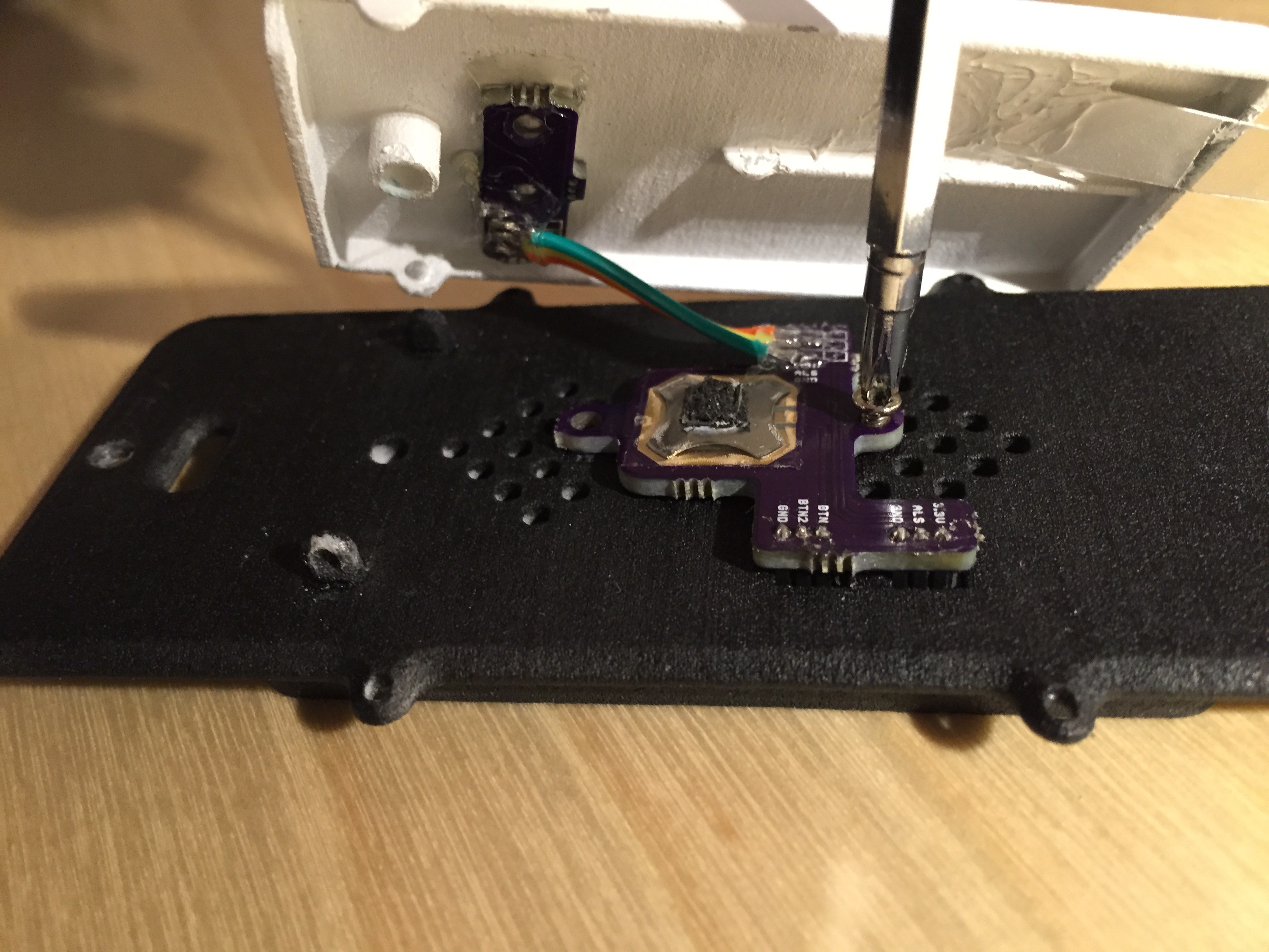
The button being screwed into place
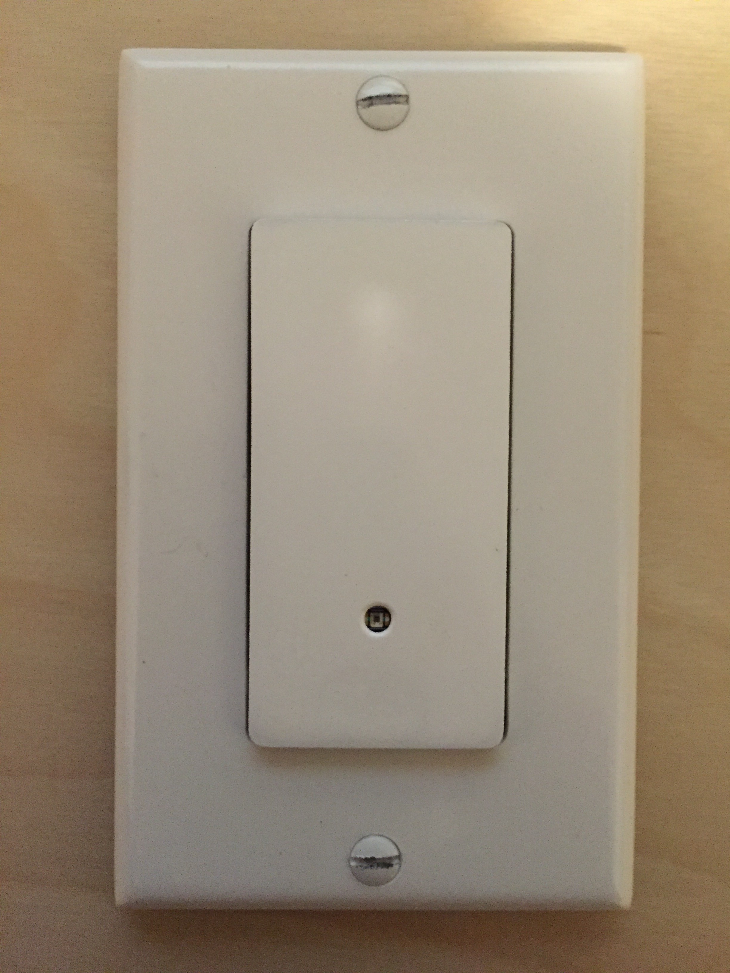
Test fit with face plate
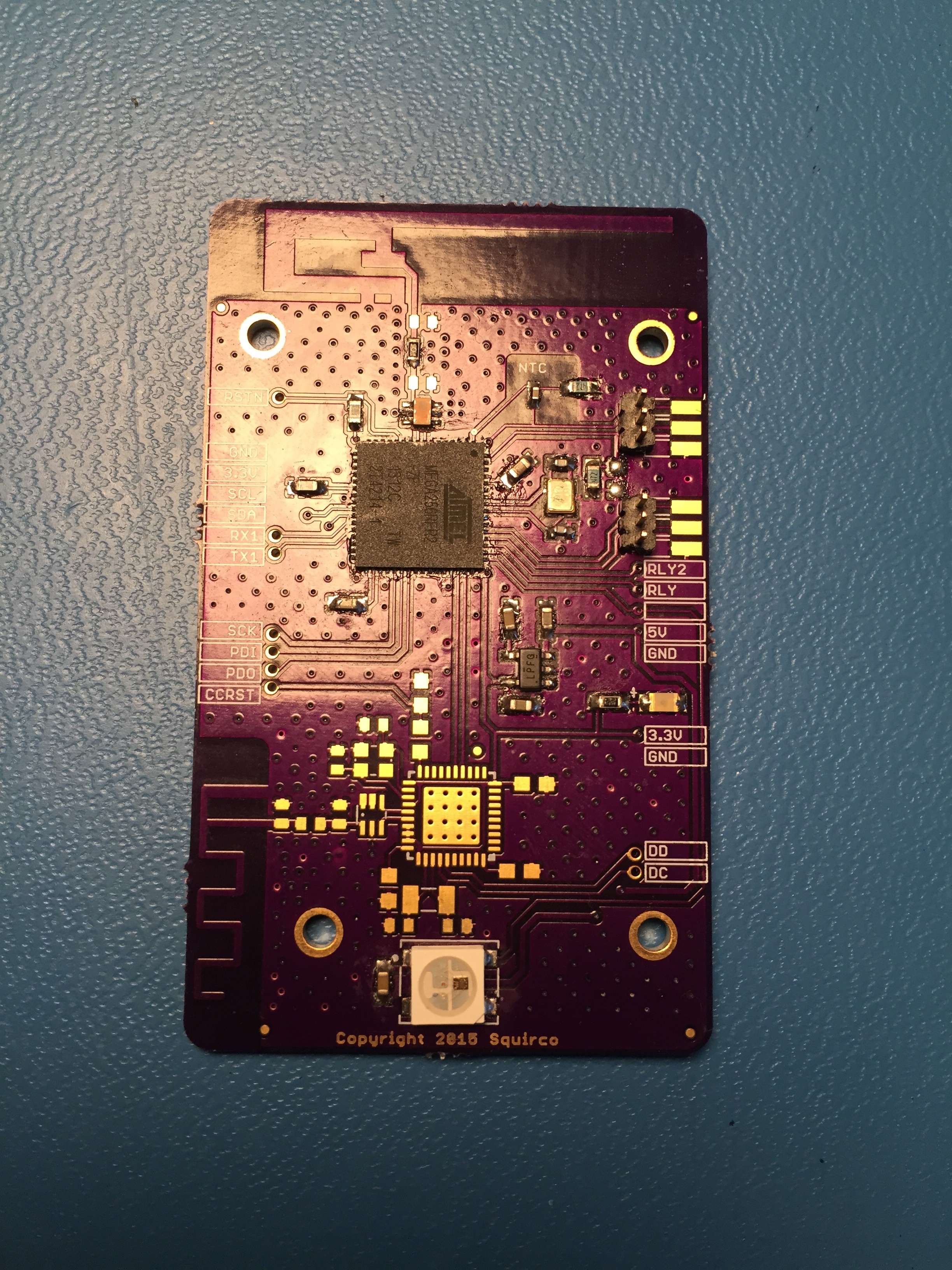
Populated PCB. CC2541 (iBeacon) is not populated at this time. It will be assembled and tested at a later date.
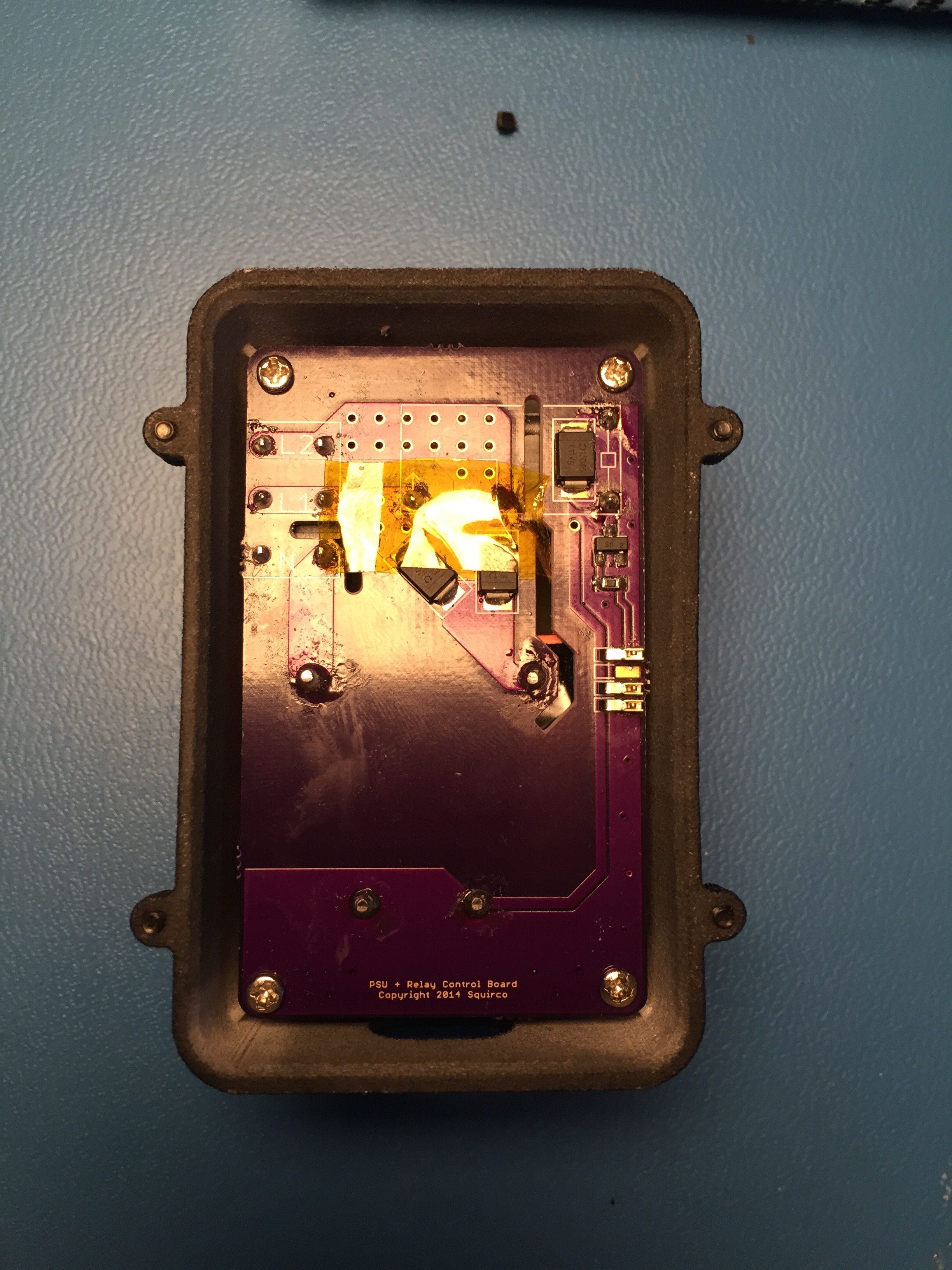
Power supply in box. A piece of kapton tape is taped over the diodes and some terminals because I am insecure.
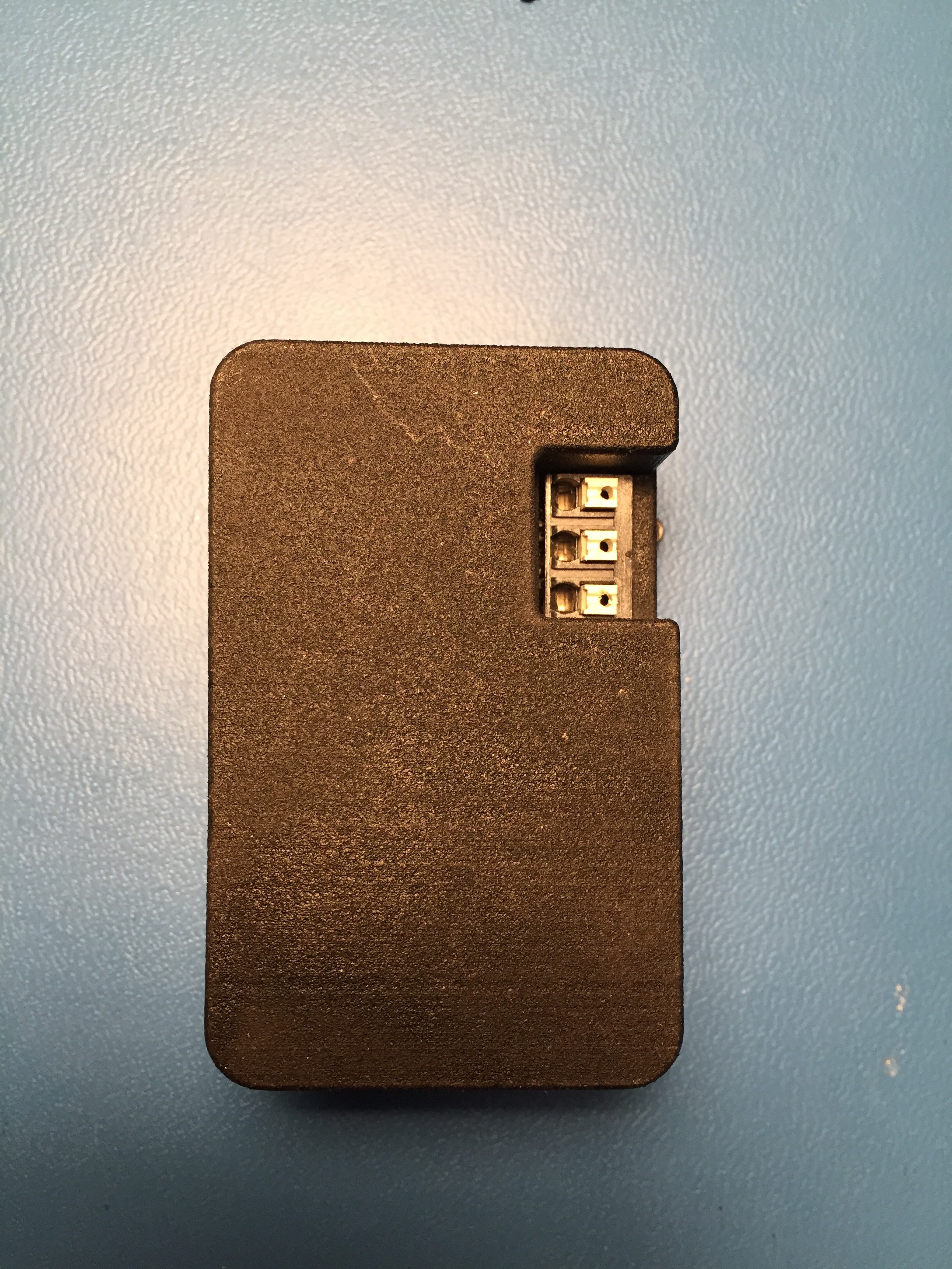
Box back view
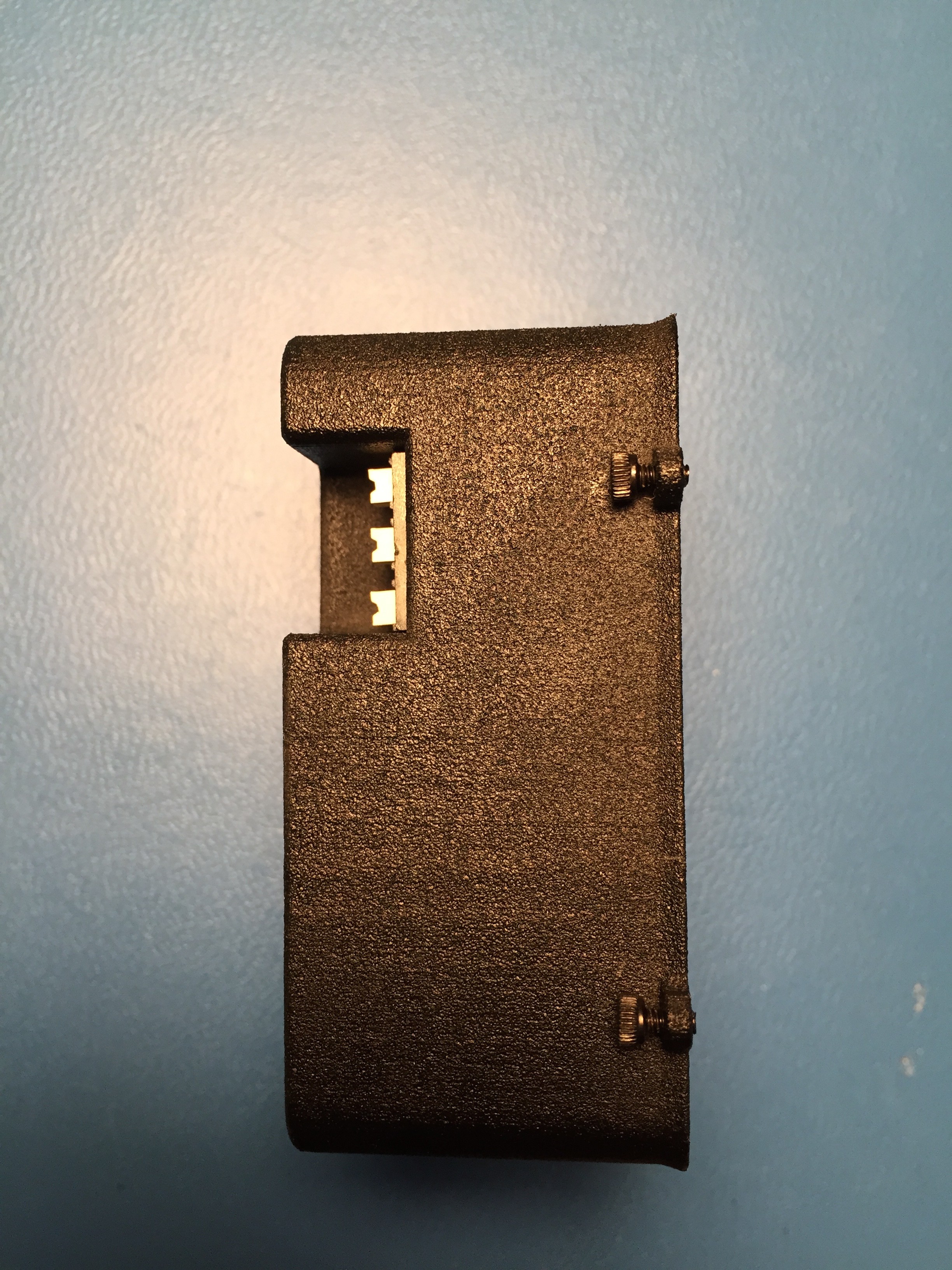
Box side view
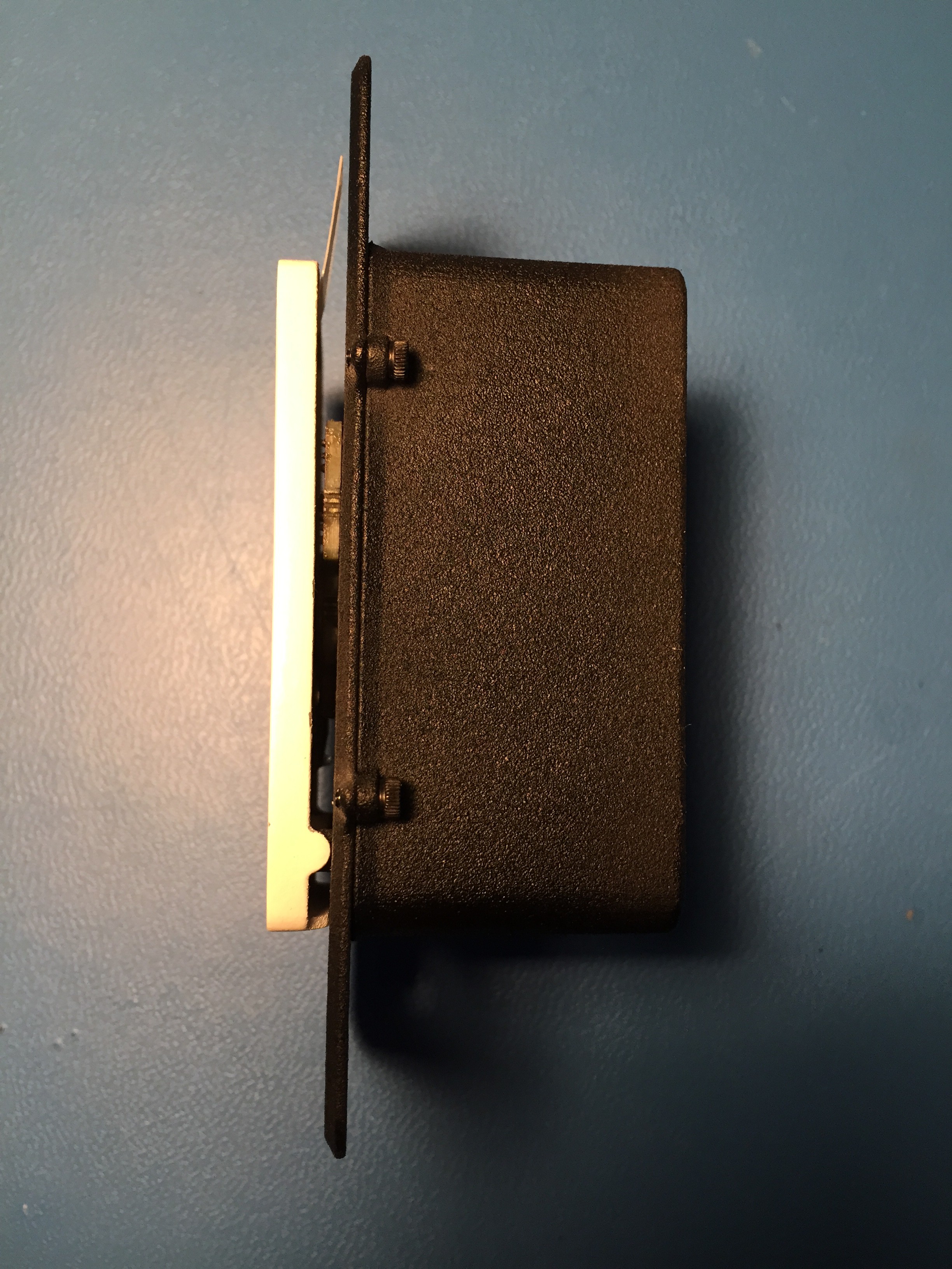
Assembled light switch, side view
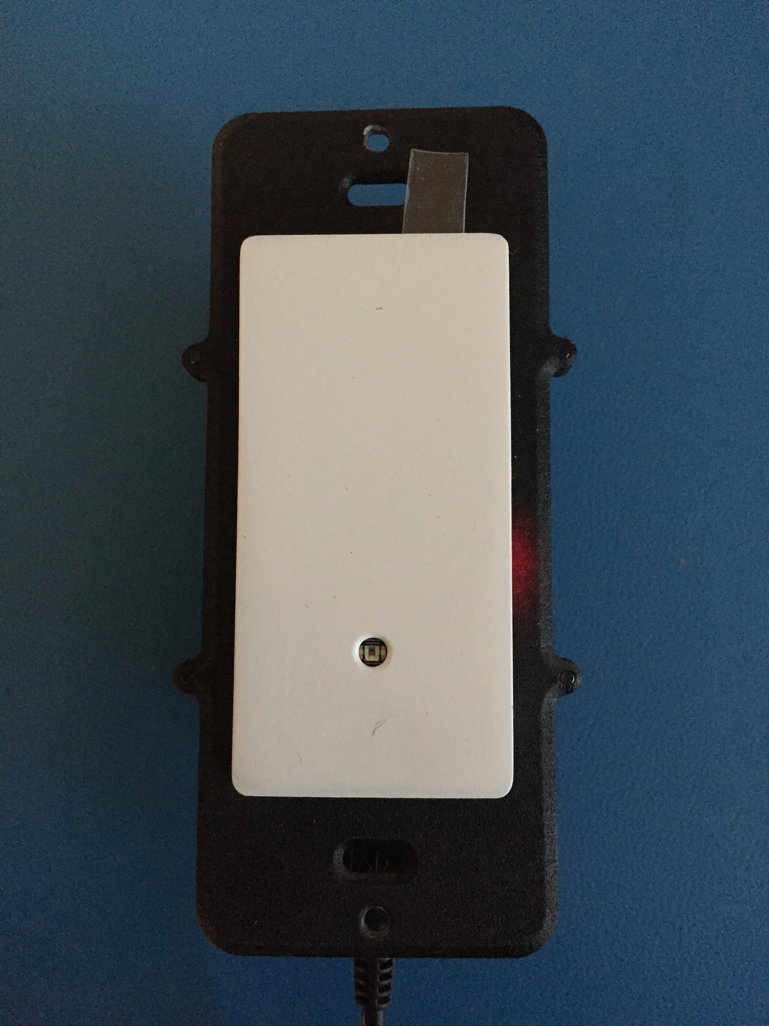
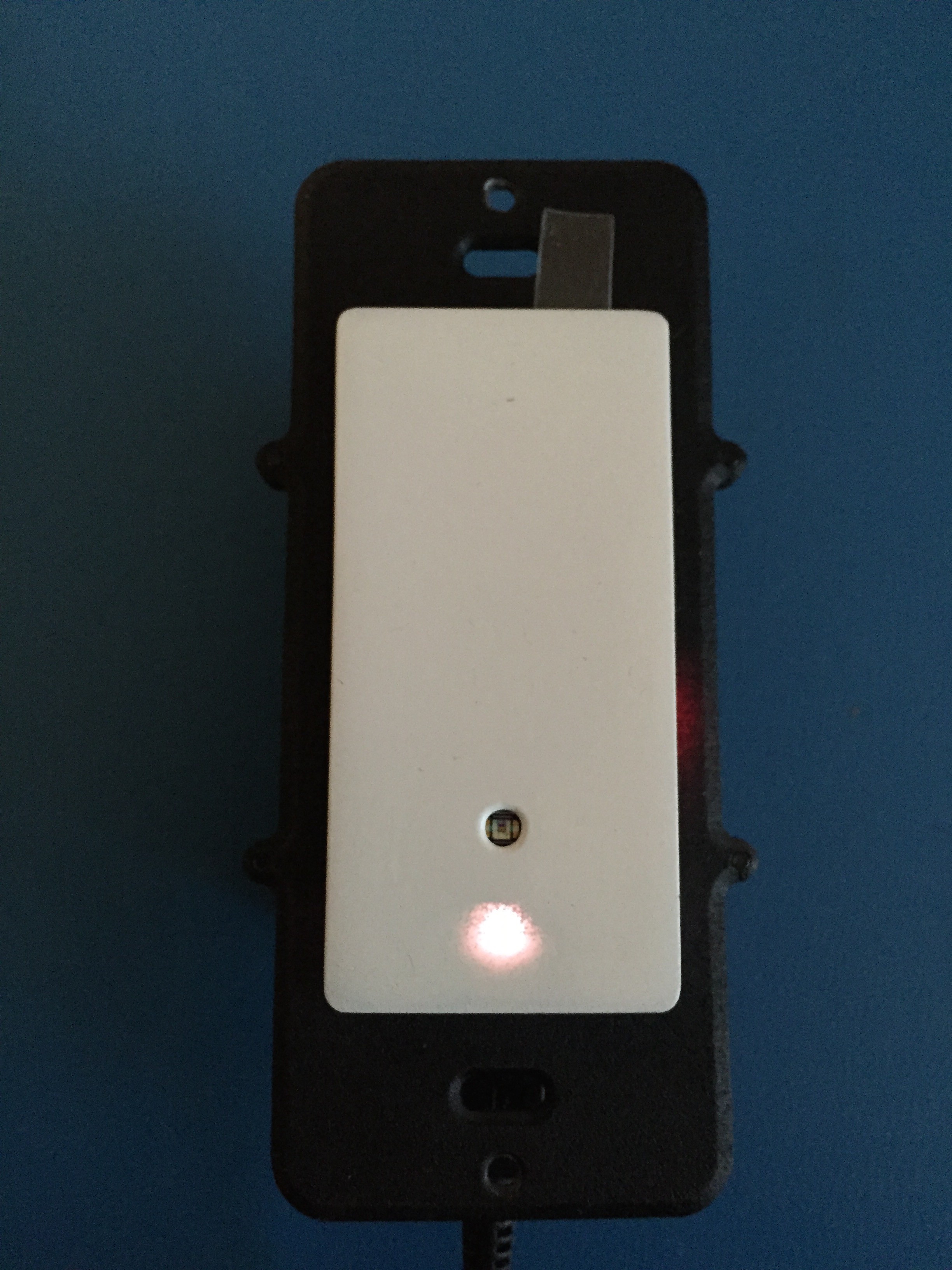
Front view again, powered on via micro usb. The power indicator is diffused through the 3D printed case and will be invisible once the face plate is on (or when assembled with proper plastic)
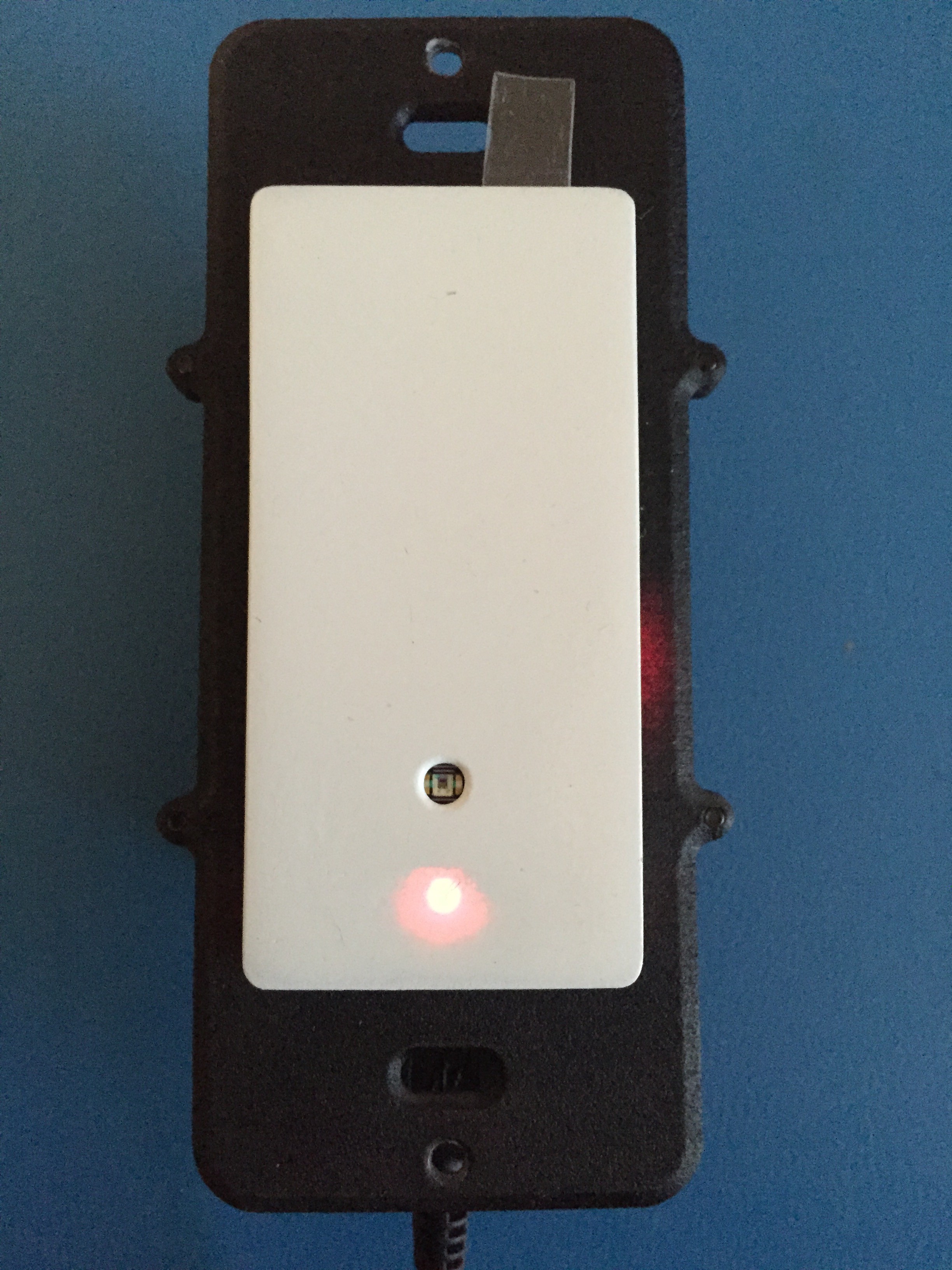
Testing hidden indicator LED. It shows up worse here than in real life because my iPhone camera is easily saturated.
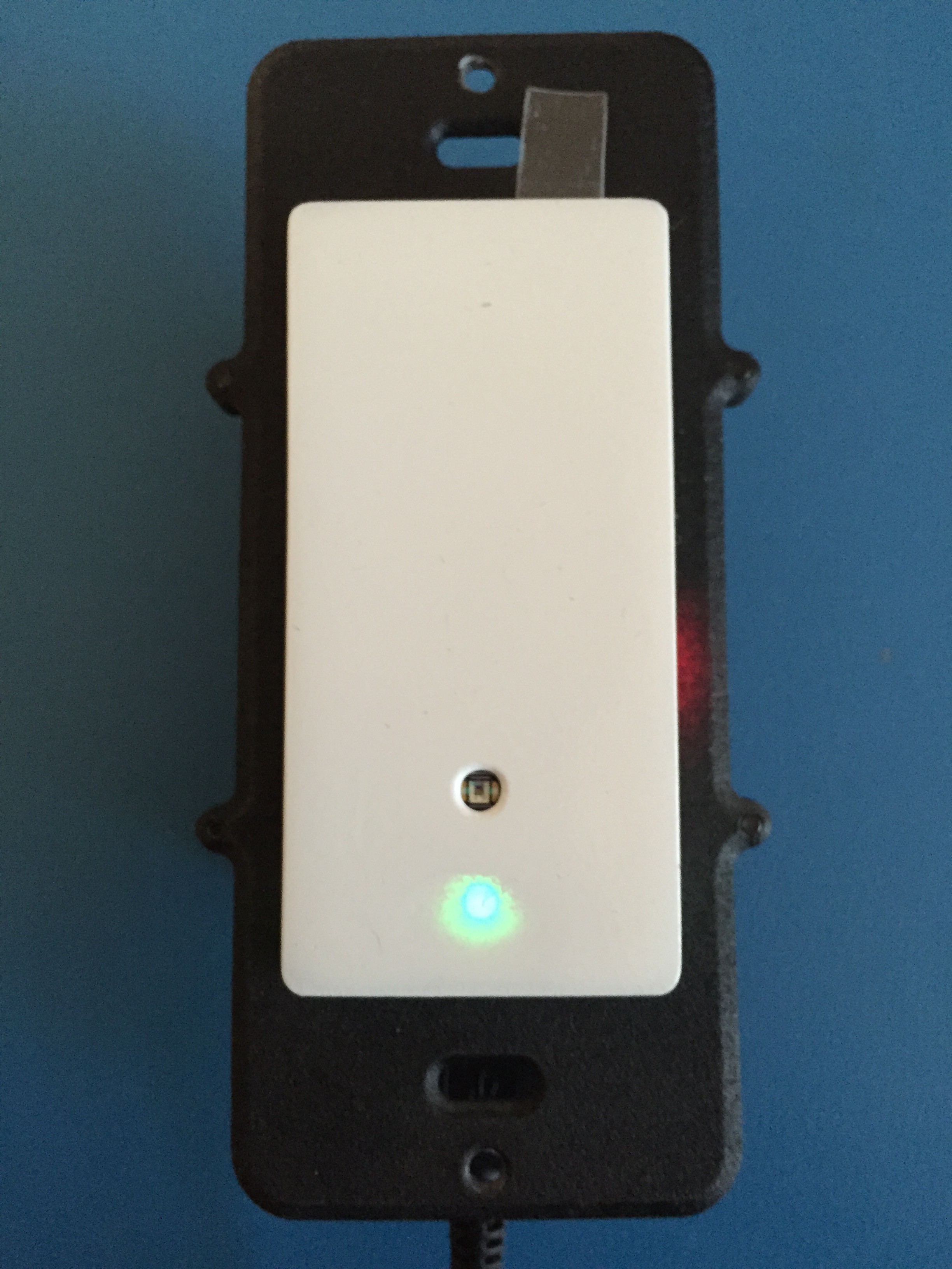
Green
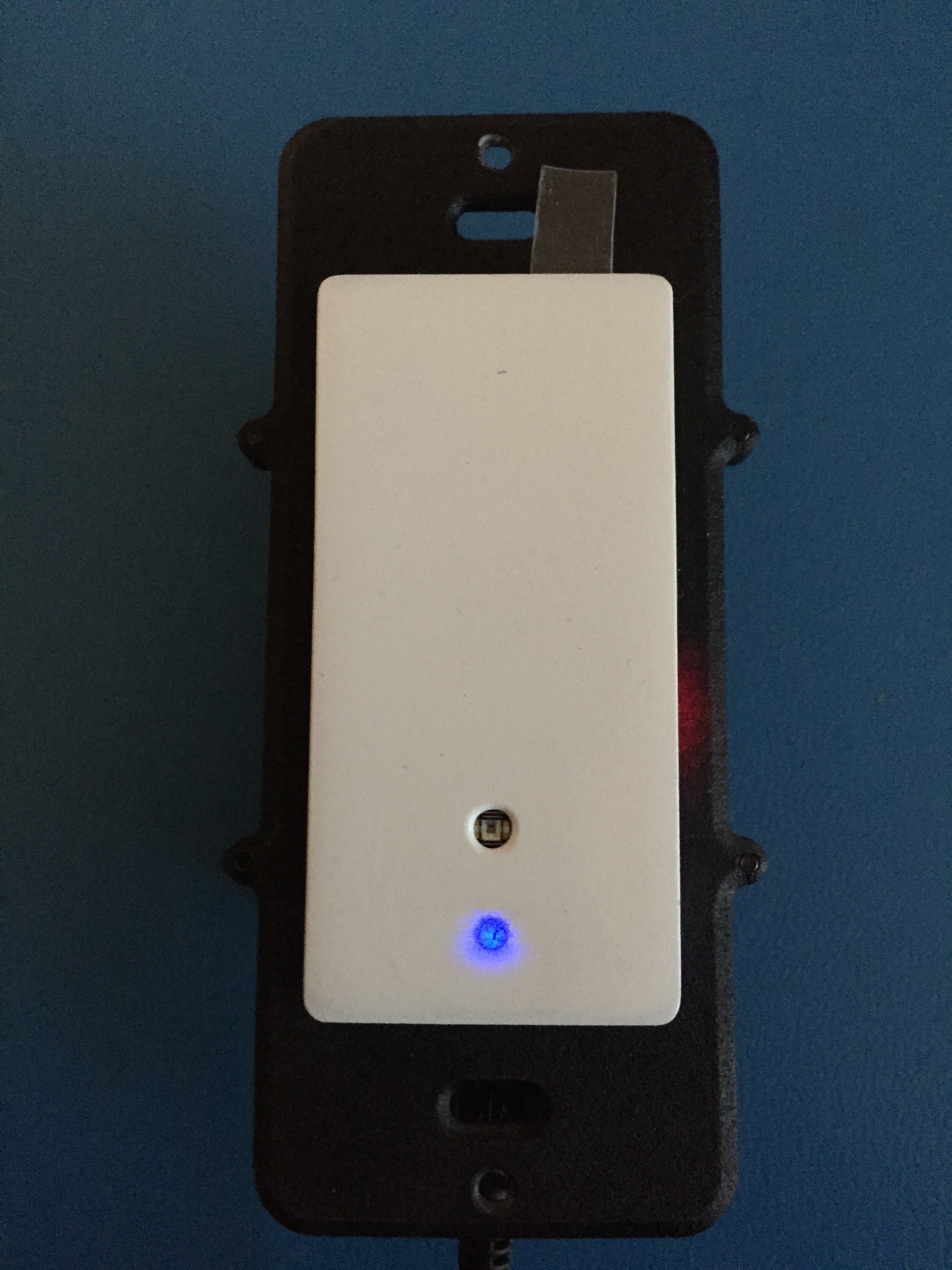
Blue
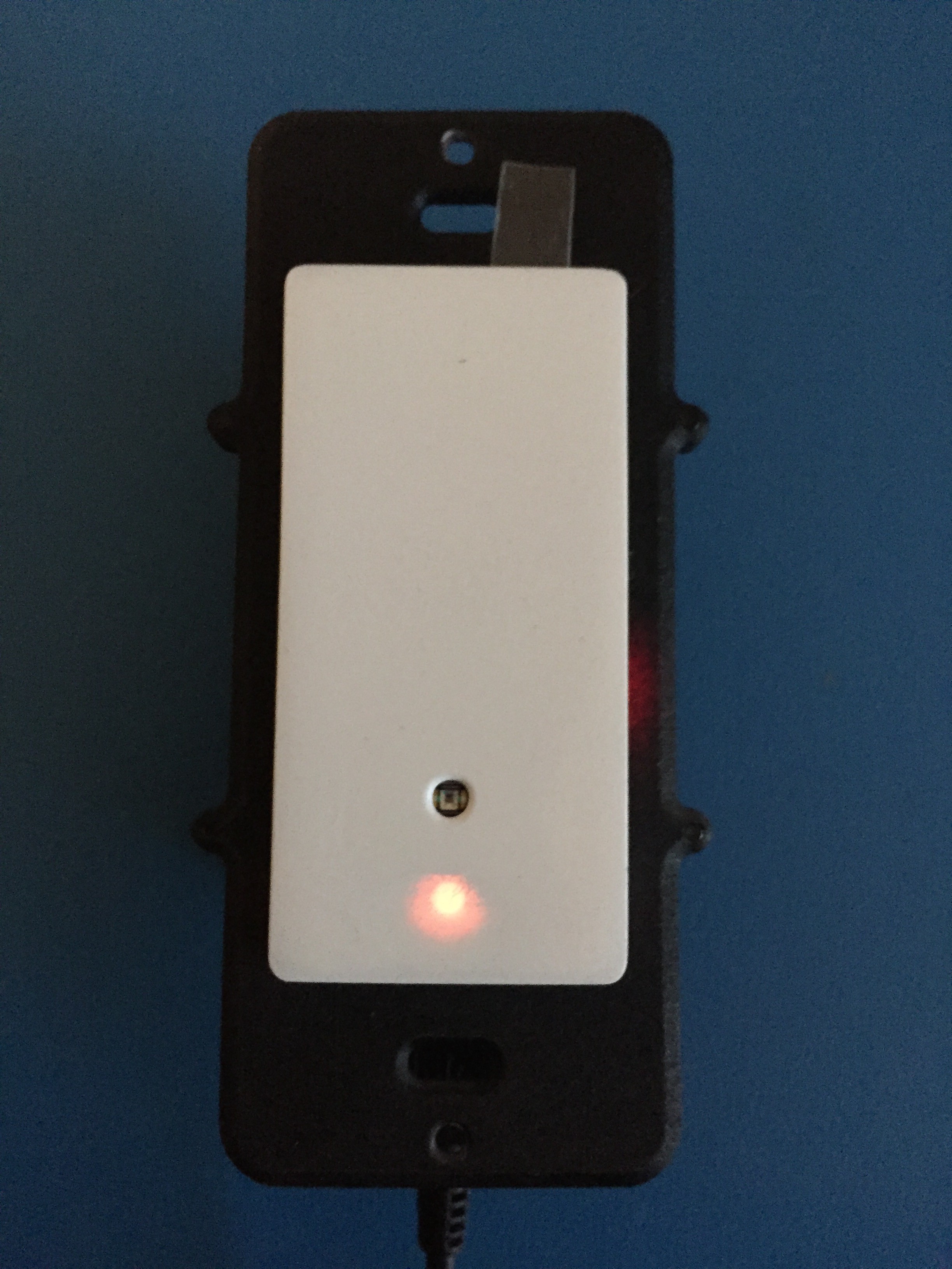
Orange
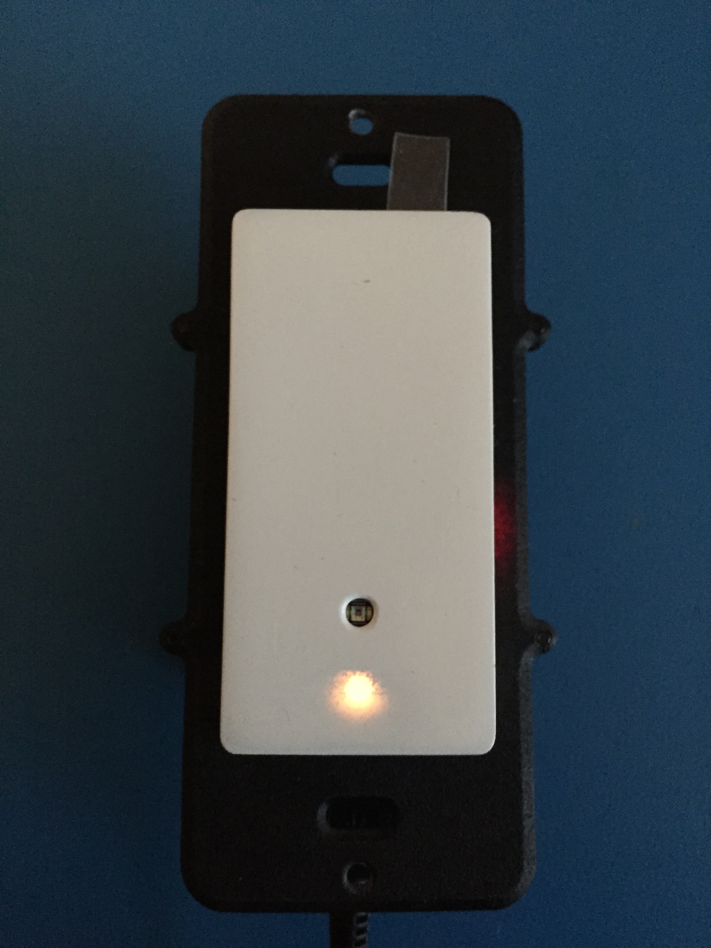
Yellow
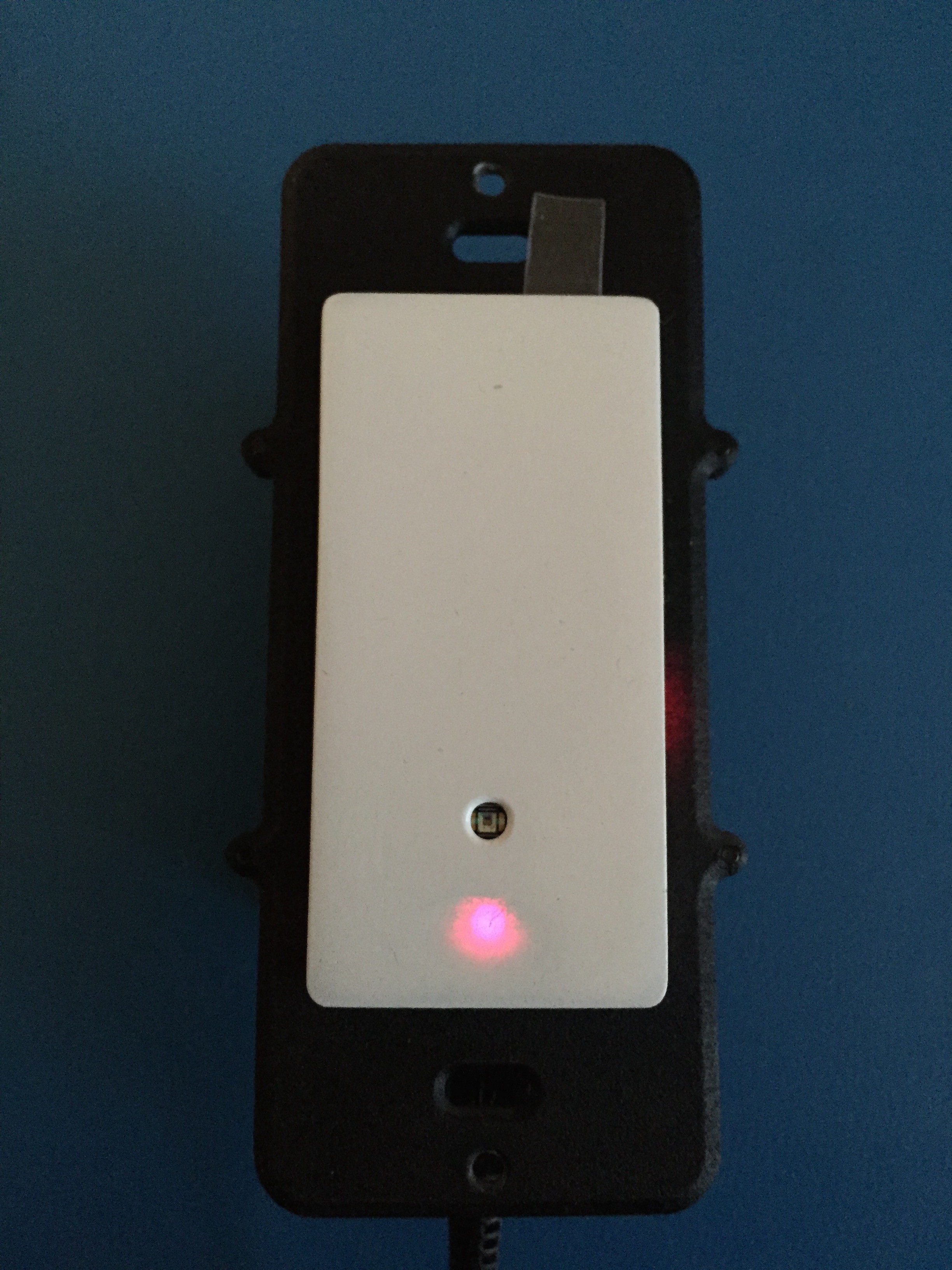
Pink
White

Off
The next step is to test the rest of the circuit to make sure no errors popped up between revisions. Stay tuned!
Discussions
Become a Hackaday.io Member
Create an account to leave a comment. Already have an account? Log In.