 willbaden
To prevent the Arduino voltage regulator from fluctuating, a 5V L7805CV voltage regulator was added. This will power the relay board that turns the loads on and off. The battery under test will be supplying the power for the relay board. This is being tapped off the 12V voltage divider on the top prototyping board. Here is a picture of the completed regulator:
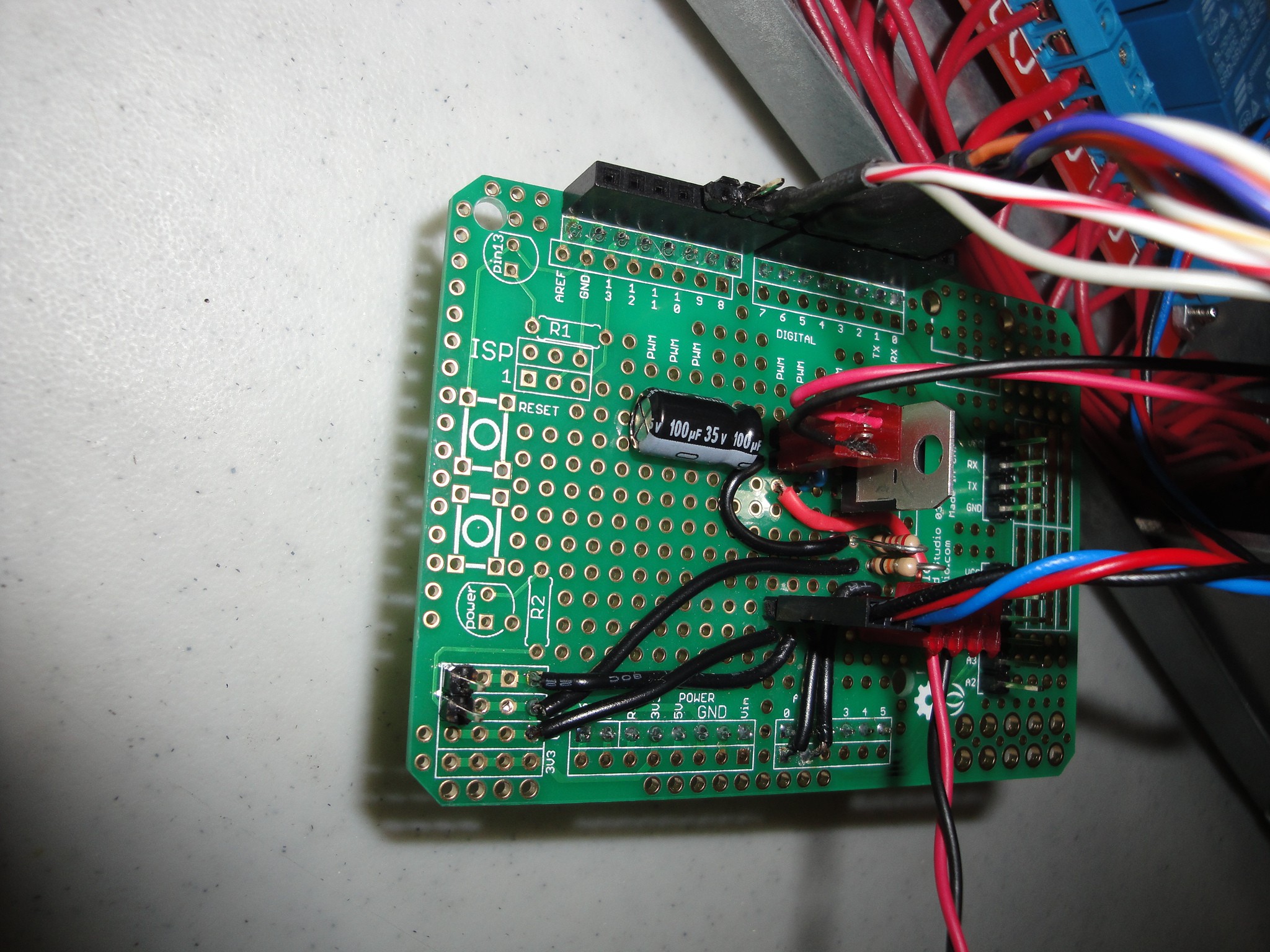
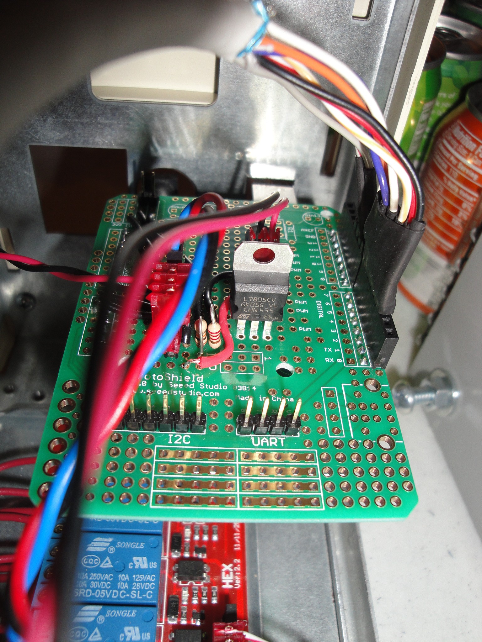
The 100uF capacitor is on the output side of the regulator. The Red connector to the right of the cap is the power out to the relay board and the L7805 is next to the connector. Between the connector and regulator are the .33 and .1 capacitors of the regulator. They can't be seen in the above photo. In the photo below is another view of the board but now it is installed on the UNO.
The next step is to test it out.
Discussions
Become a Hackaday.io Member
Create an account to leave a comment. Already have an account? Log In.