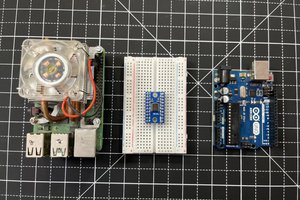
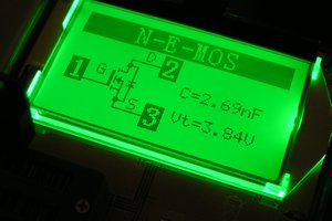
The circuit is very simple.
The heart of the device is a voltage comparator TLC3702IP able to compare the voltage levels on its input pin , emitting a voltage level output based on the result of the comparison.
On a first pin reaches the voltage read from the tip ( nail welded copper , excellent electrical conductivity ) , on a second pin instead read a reference voltage for the high logic level , in this case 5V .
Here the formula that determine the level of output voltage :
- + Vcc is the positive power supply voltage ( 5V )
- -Vcc is the negative power supply ( GND )
- Vr is the reference voltage for comparison
This control Vout goes through an additional circuit , an RG LED (LED 3-pin ) that glows red to green and low logic level to a high logic level.
 M.i.P.studio


 Lithium ION
 RoGeorge
 drhatch
 mircemk
K.C.Lee I don't understand what you write, bad documentation and bad explanation...