Made some tests during the week on a breadboard. Tested PWM on a MOSFET, the LCD, made a table with the PTC resistance in the 30C ~ 450C range, etc.
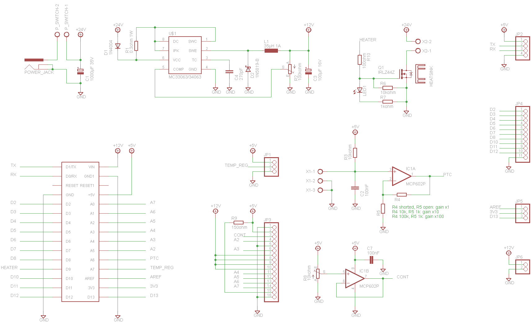
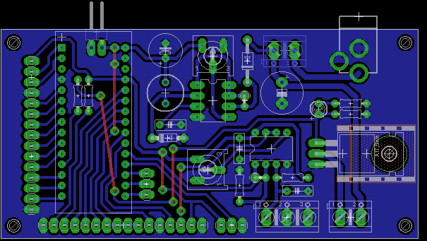
After I decided how to build the hardware, went to Eagle and created the schematics and board.
The chosen MCU is an Arduino Nano, and the operational amplifier a MCP6002, cause I have some laying around. Any op. amp. that works with 5V power supply, is rail-to-rail, and have the same pinout should work.
Schematics:

Board:

The board fits in a 5x10cm copper board. As I made it to be easily toner transferred it was rather hard to route it after all the time doing two-sided boards with 8mil tracks.
I'll probably etch one of these tomorrow at college. They have a good heat press I can use to transfer boards there.
 Kuro
Kuro
Discussions
Become a Hackaday.io Member
Create an account to leave a comment. Already have an account? Log In.
The toroid is 160W(VA). 2 x 26V @ 3.2Amp. I picked it up cheep on ebay because it's close to the the right voltage so I will make the solder station with two irons to save me changing tips as often.
I will be driving the iron with AC so I will switch with a TRIAC. I will also have to wrap a couple of dozen turns of wire around the toroid for the lower voltage micro-controller supply. I will also use Zero voltage switching.
I metered the iron I have (new) and it has a heater resistance of 3.1 Ohms or 185 Watts at 26 Volts so I am assuming it is not linear. The PTC? is about 47 Ohms.
I can't make circuit boards here yet. I am trying the toner transfer method and I am having a lot of trouble. I bought another laser printer and it seems to work much better (lower melting point toner) but still far from good.
And for gertjan.debruycker -
The pinout looking at the end of the plug or the back of the socket going clockwise from the left with the notch at the bottom is Heater, Heater, Tip Ground, PTC, PTC.
Are you sure? yes | no
Pin numbering is different. Hakko goes - anti-clockwise from right, 1, 2, 3, 4, 5
The Din standard goes 1, 4, 2, 5, 3
The hakko specs for this iron are - heater 2.5 - 3.5 Ohms, PTC 43 - 58 Ohms at room temperature.
Are you sure? yes | no
Are you sure? yes | no
http://www.hakko.com/english/maintenance/topic_station_type_2.html
Notice that in Hakko 936 schematics, the 1M resistor goes to the connector sleeve, not the ESD (tip) pin.
http://dangerousprototypes.com/forum/download/file.php?id=4702&mode=view
Are you sure? yes | no
yours sincerly GJ
Are you sure? yes | no
After measuring the resistance x temperature table, I noticed the resistance variation of the PTC is almost linear with temperature, so I adapted fitted it to a first degree equation. The values of A and B will change according to the amplification on the operational amplifier.
I used a ~47x amplification (47k and 1k resistor). The equation I got from this: T = 1.16*V - 234.48, where T is temperature in Celsius and V is the analog value read from the Arduino pin.
The CONT operational amplifier is used to set the LCD contrast. I know I could use a pot to set it, but I intend to use other display in the future and I'll need a precise voltage reference. The second amplifier was not being used anyway.
I'll post updates later when I get the time.
Are you sure? yes | no