 SimpleTronic
PWM Power LED dimmer:

Quick Tour Video:
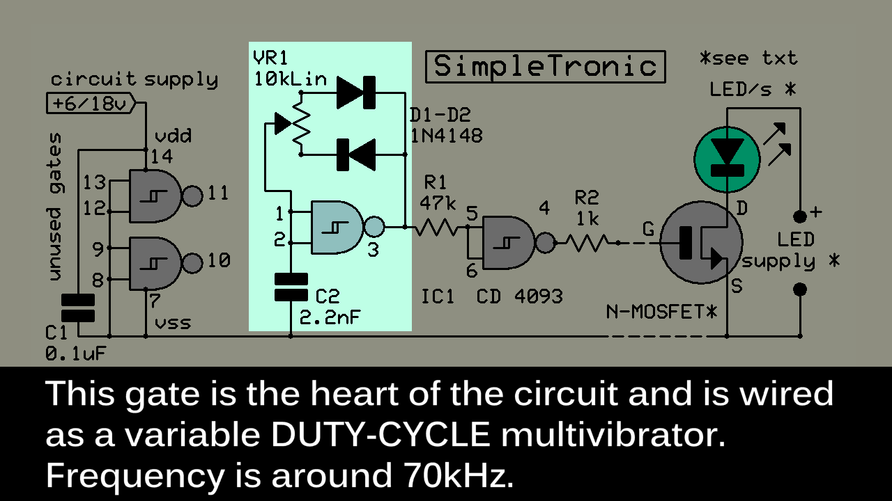
Operation Principle:
When output is 1 (high) capacitor C charges through resistor R.
When C voltage reaches the HIGH THRESHOLD, gate out inverts & falls to logic 0.
Now capacitor C discharges through resistor R.
When C voltage reaches the LOW THRESHOLD, gate out inverts & rises to logic 1.
This sequence repeats & generates a 50% duty cycle square wave output ( at a frequency of around 70KHz)
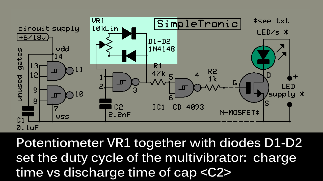
Variable Duty Cycle:

By separating the charge & discharge paths with a resistor and a diode, we can alter the DUTY CYCLE that is, the ON time vs the OFF time.
Replace resistors with a potentiometer, and you have a continuously variable duty cycle multivibrator .
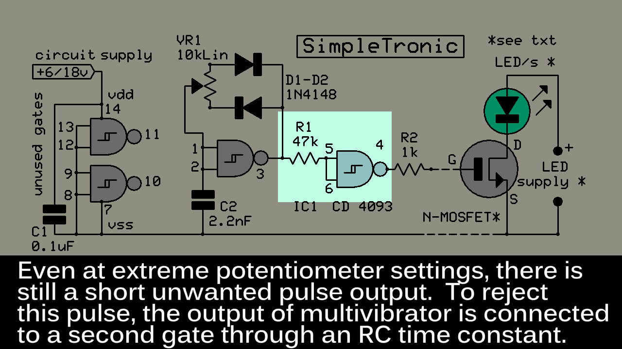
Circuit Diagram:
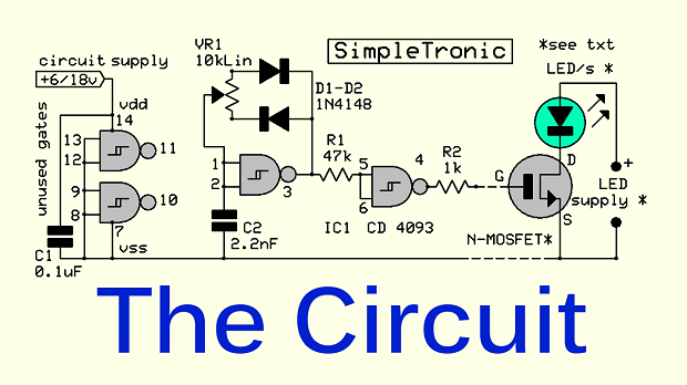
Circuit Operation Details:
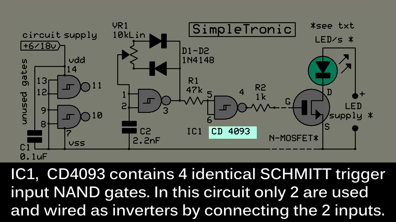
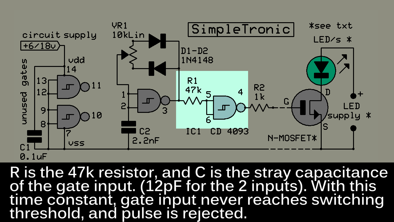
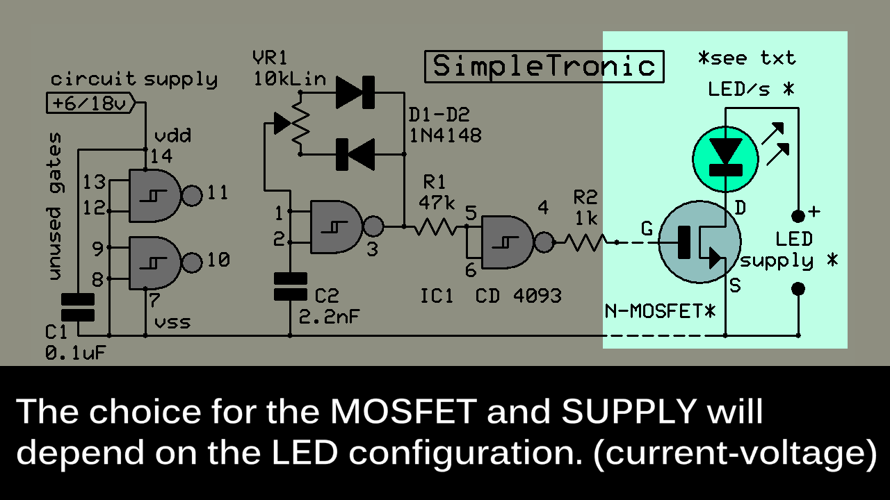
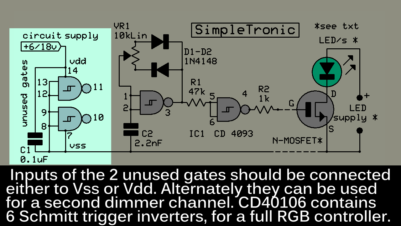
The specific FET and supply for the LEDs will depend on the required current-voltage of the led array. Supply can be a constant current source or constant voltage one with a small value series resistor, and with an output voltage slightly above the total led forward voltage drop.

 Pnoxi
Pnoxi
 Hulk
Hulk
 Kevin LO
Nice, I see you solved the zero problem as well.