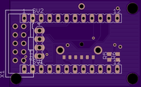
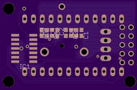
After finally settling on what the system needs I put together a quick schematic and board in Eagle. This is far from my best work, but I was in a hurry to get it out to OSHPark because of the turn around time. In the event that the PCB doesn't come in with enough time to spare I suppose I'll just have to deadbug everything! ;)
This PCB should allow me to fit everything into a case that is 30mm wide, 100mm tall, and 20mm thick.
Without further ado, here's a bit of an overview of the PCB.
On the top I will be mounting the output port, the I2C OLED screen, 2 pullup resistors, and rotary encoder. I chose the 2x5 IDC connector for the output port because I just happened to buy a bus pirate and can reuse the clip leads that I bought with it. The outputs are as follows.
- 2 analog buffered outputs
- 2 digital buffered outputs
- 2 digital unbuffered outputs
- RX
- TX
- 5V
- Ground

On the bottom I have 2 low pass filters and a quad op amp. The Trinket Pro will also be on this side. I designed the filters using a Sallen Key filter design tool that my friend made. He will eventually make this public once he cleans it up, but it is pretty easy to use as long as you know a bit of python currently.

 gannon
Discussions
Become a Hackaday.io Member
Create an account to leave a comment. Already have an account? Log In.