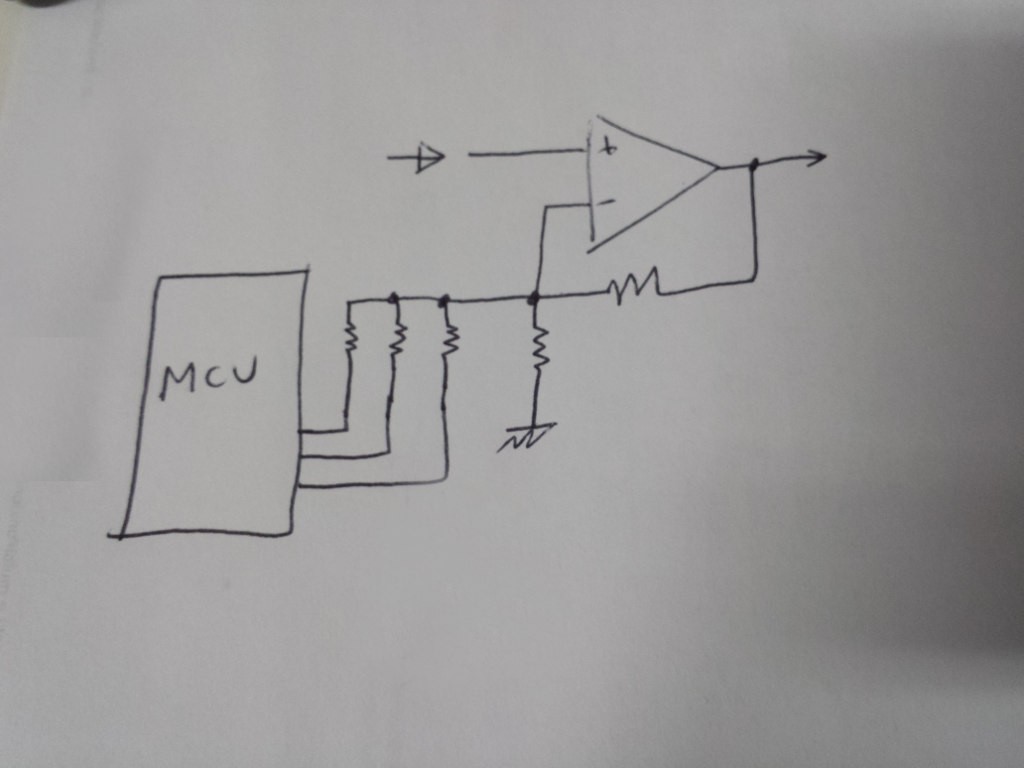
PGAs are quite common, but I don't have one in my parts bin and I was curious about an idea I had for a while. The opamp gain is set by the two resistors ratio, and since one of them is grounded, I can add a resistor in parallel by connecting it to the MCU I/O and grounding the pin or setting it as an input to activate or deactivate it.

I looked around the web but couldn't find anyone supporting/bashing my theory (if someone has links discussing this, please let me know), so I just tried it and it works! With an ATMEGA328P you must connect the resistor to an analog pin, or else it will still load it too much when set as an input. Setting the pin to analog input will leave the resistor floating, and setting it as a low output will connect the resistor to ground. This setup is not perfect, especially at low voltages, and it seemed to further reduce the bandwidth at high gains.
BTW, I'll be using a TI PGA113 with a 10Mohm 1:10 divider as an input. I calculated the measurable voltages, and with that setup I should be able to go up to about 30V. I may add a switchable resistor to further decrease the gain to 1:100, I'll test it when I get the PGA.

 Mastro Gippo
Discussions
Become a Hackaday.io Member
Create an account to leave a comment. Already have an account? Log In.