PLYWOOD EXCAVATOR - THE BUILD...
- - - Massive thanks to Steve Knight the ultimate tinkerer for letting me use his mind and his workshop - - -
I have followed projects showcased here on Hackaday for what now seems like forever. It never ceases to amaze me the ingenuity of people featured so Its my absolute pleasure to post this project here... Thanks Hackaday!
Not entirely sure where to start so apologies if this project reads badly, just look at the pretty pictures and work out how I did it. I also really struggled to name all the parts or be consistent with naming of parts. I was just making it up as I went along!

Scale - At first i needed to find a suitable template to design the excavator shape and get the proportions just right to fit a 5 year old. After some googlefu I found the image below and set about scaling it to fit and tracing lines over the main elements to get a feel for the basic shape.

Safety First - obviously a small child and pinching parts is a possible recipe for disaster so I took along time to consider safety.
The most complicated part of the machine is the caterpillar tracks and It took me quite a while to figure out how this was going to work. I was conscious that a small child's fingers could get stuck in the gears and the track links, however I wanted an authentic caterpillar track look, so compromises had to be made.
Caterpillar Tracks - Initially I wanted to use plywood for everything possible even the chain links for the caterpillar track. Getting the gearing to mesh with tracks was interesting and I found gear generator program and played around until the correct number or track paddles and links where fully realised. The images below show this development.
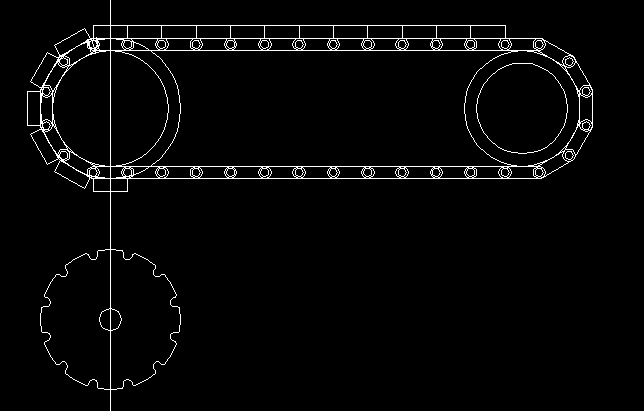
The drive gear and chain above had way to many links to be easily fabricated so I decided to reduce the number.
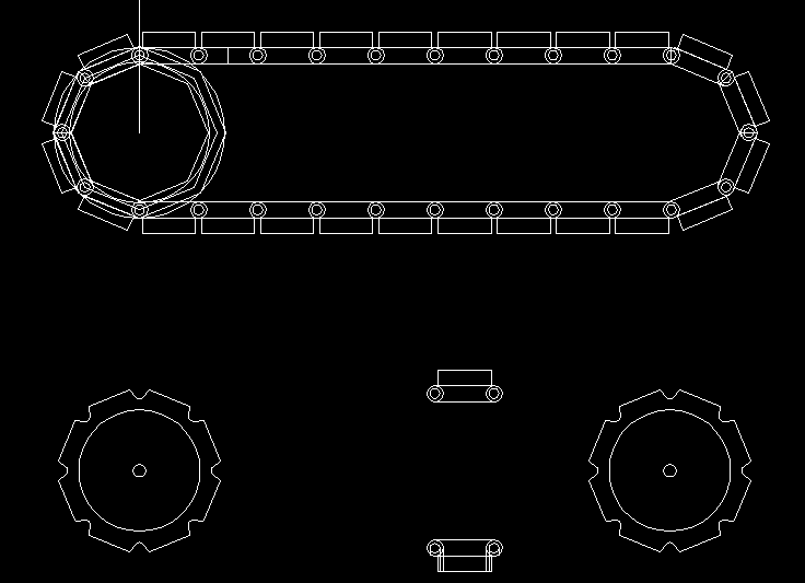
As can be seen the reduction in track links simplifies the entire design.
I then set about trying to make a very slender chain from plywood links. The images below show the machining of the links. I don't have a vacuum bed so each link had to be predrilled then screwed down before machining the profiles.
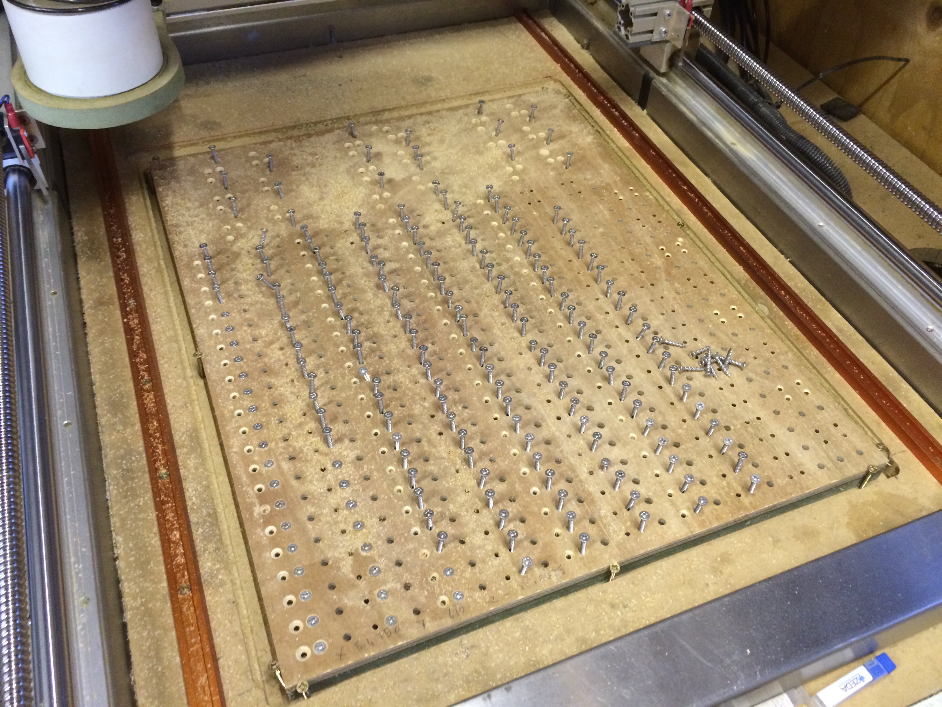
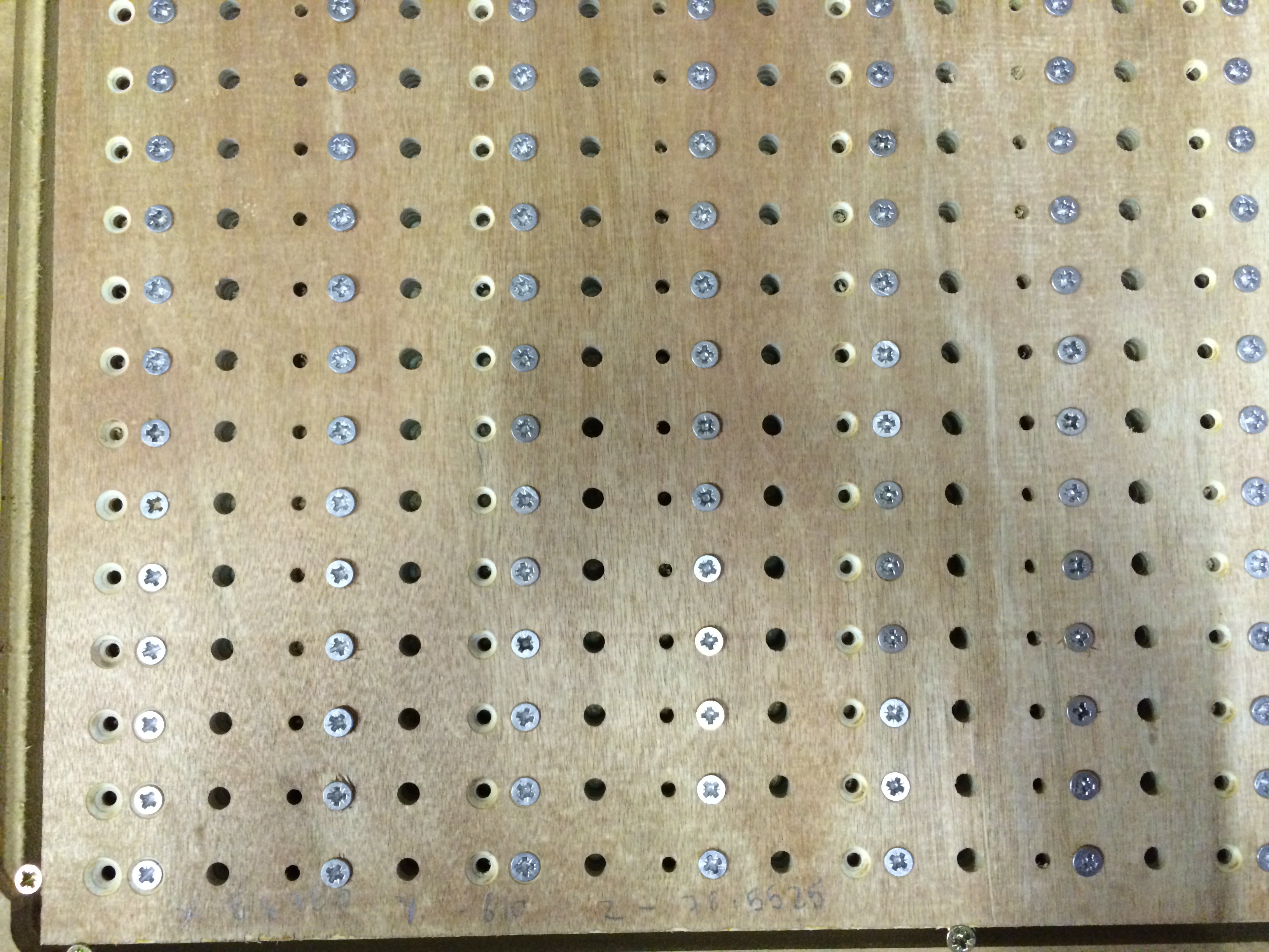
6mm holes for the pins, 3mm for the screws countersunk naturally!
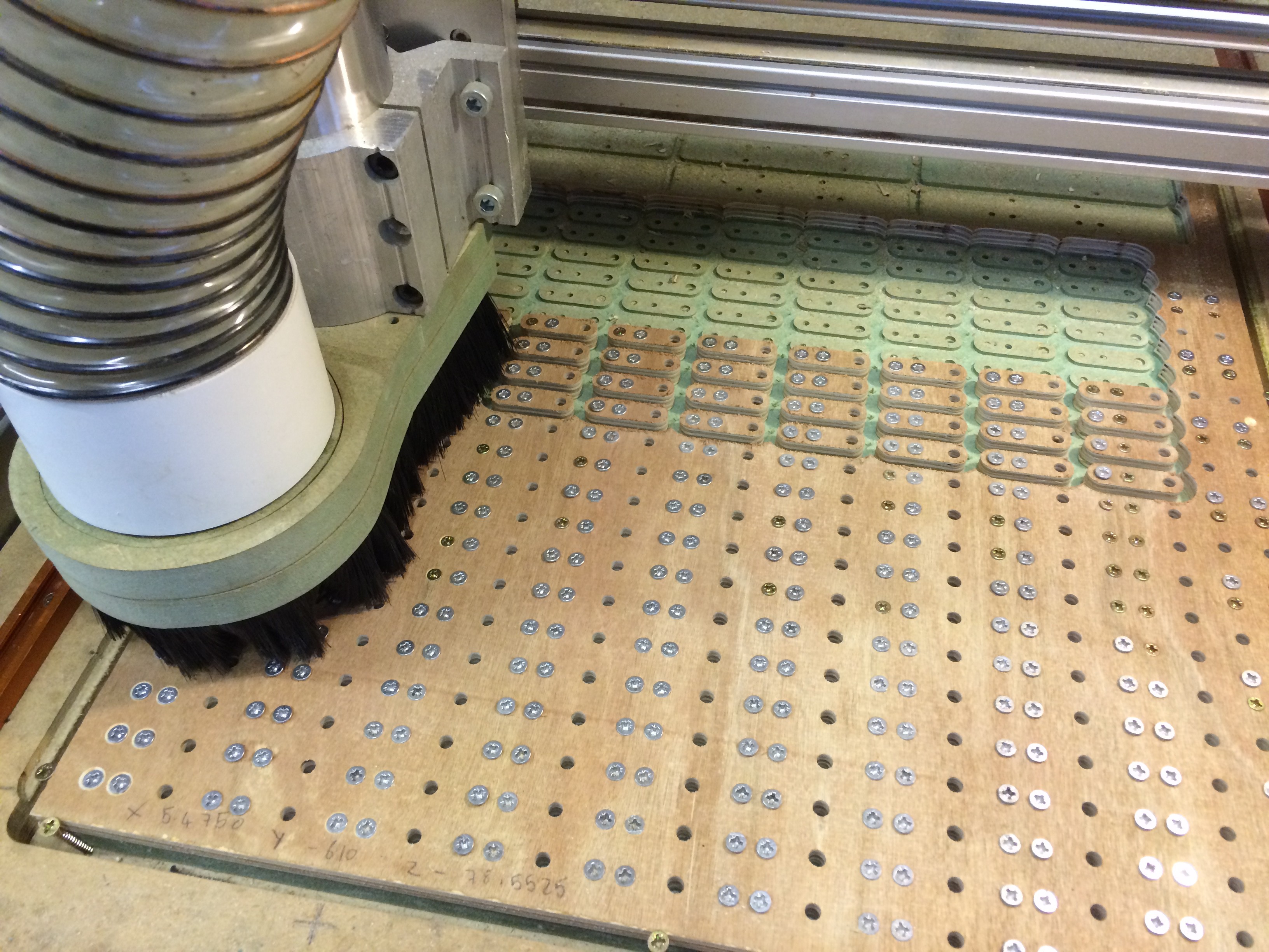
Final profile cut.
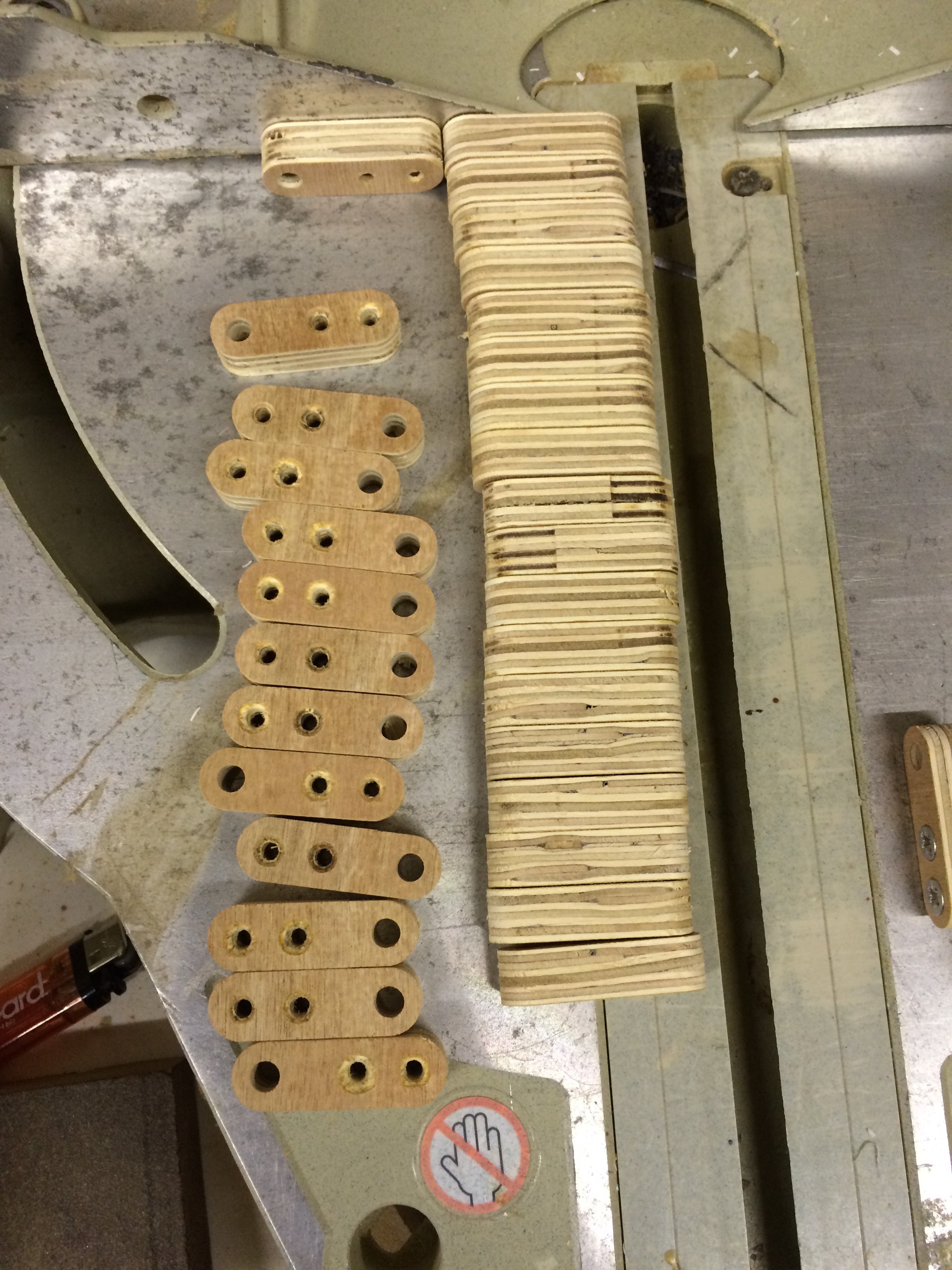
Final links ready to be stuck together. Glued and screwed with stainless screws
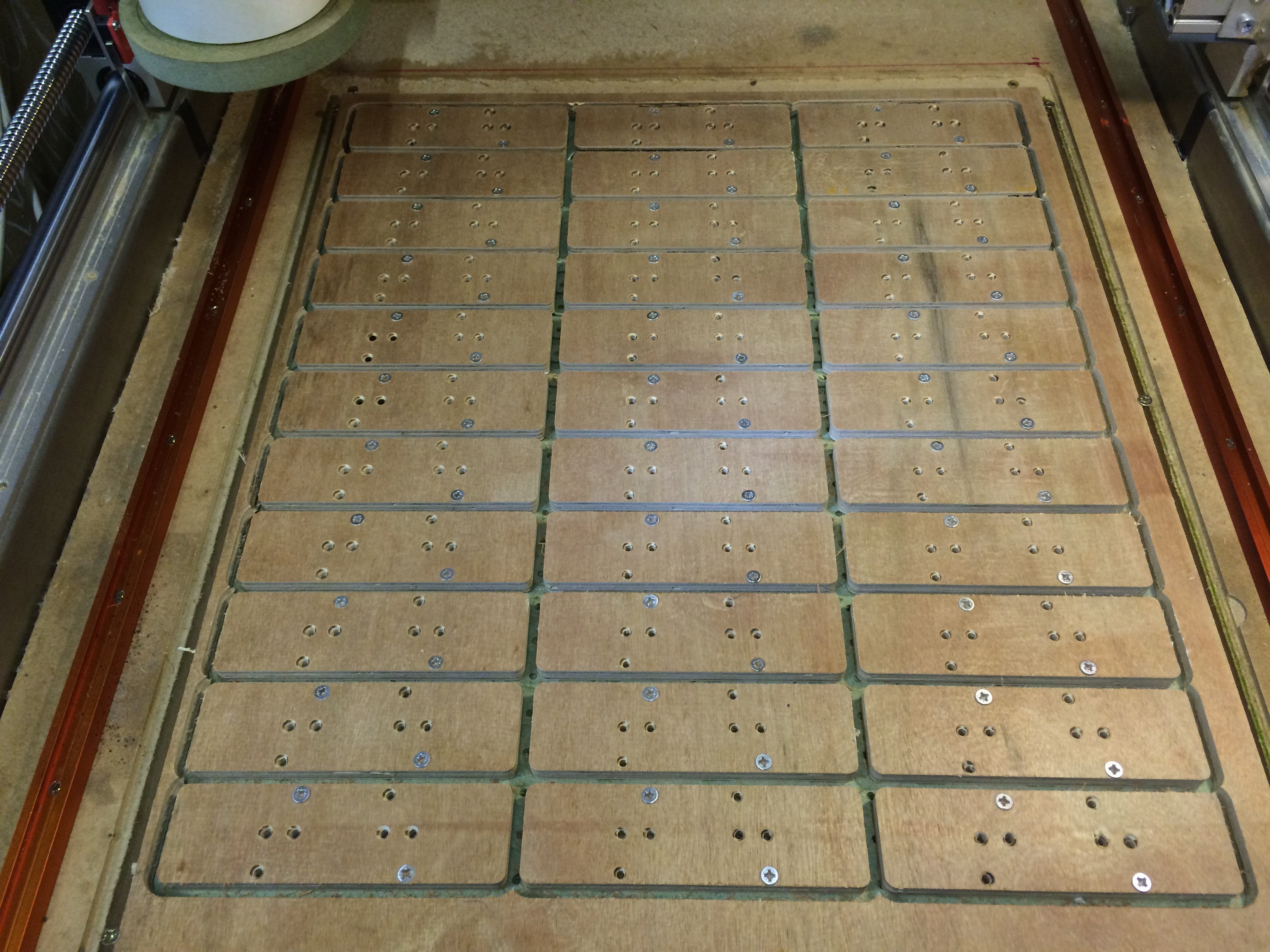
Machining out the Track Paddles / Plates? Not sure what they are called? Answers on a postcard please!
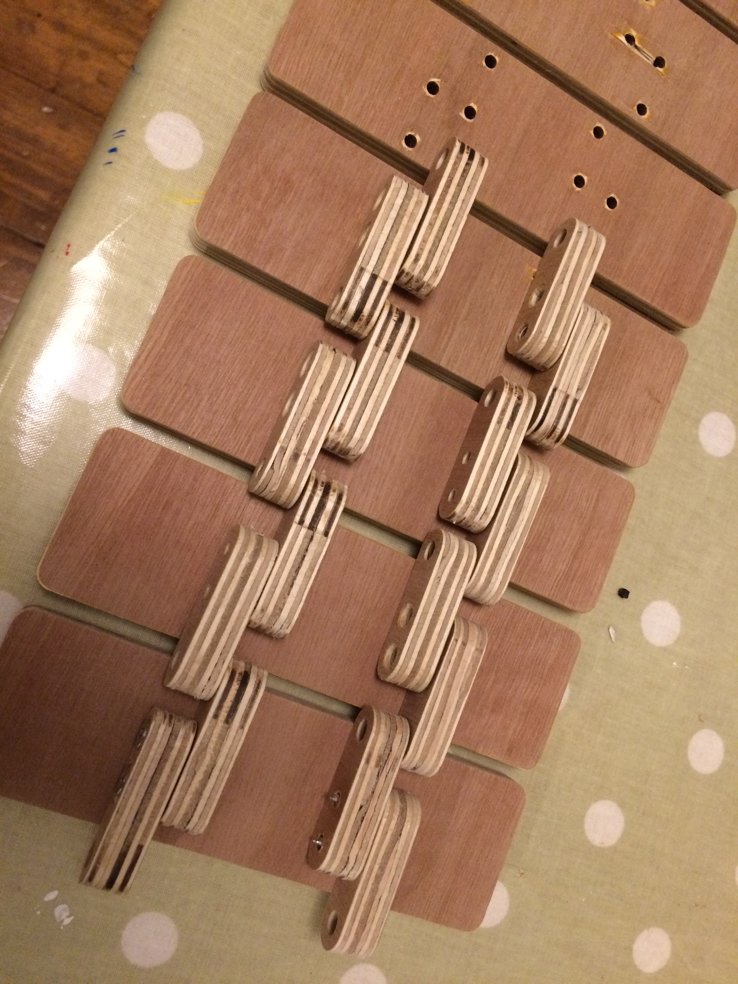
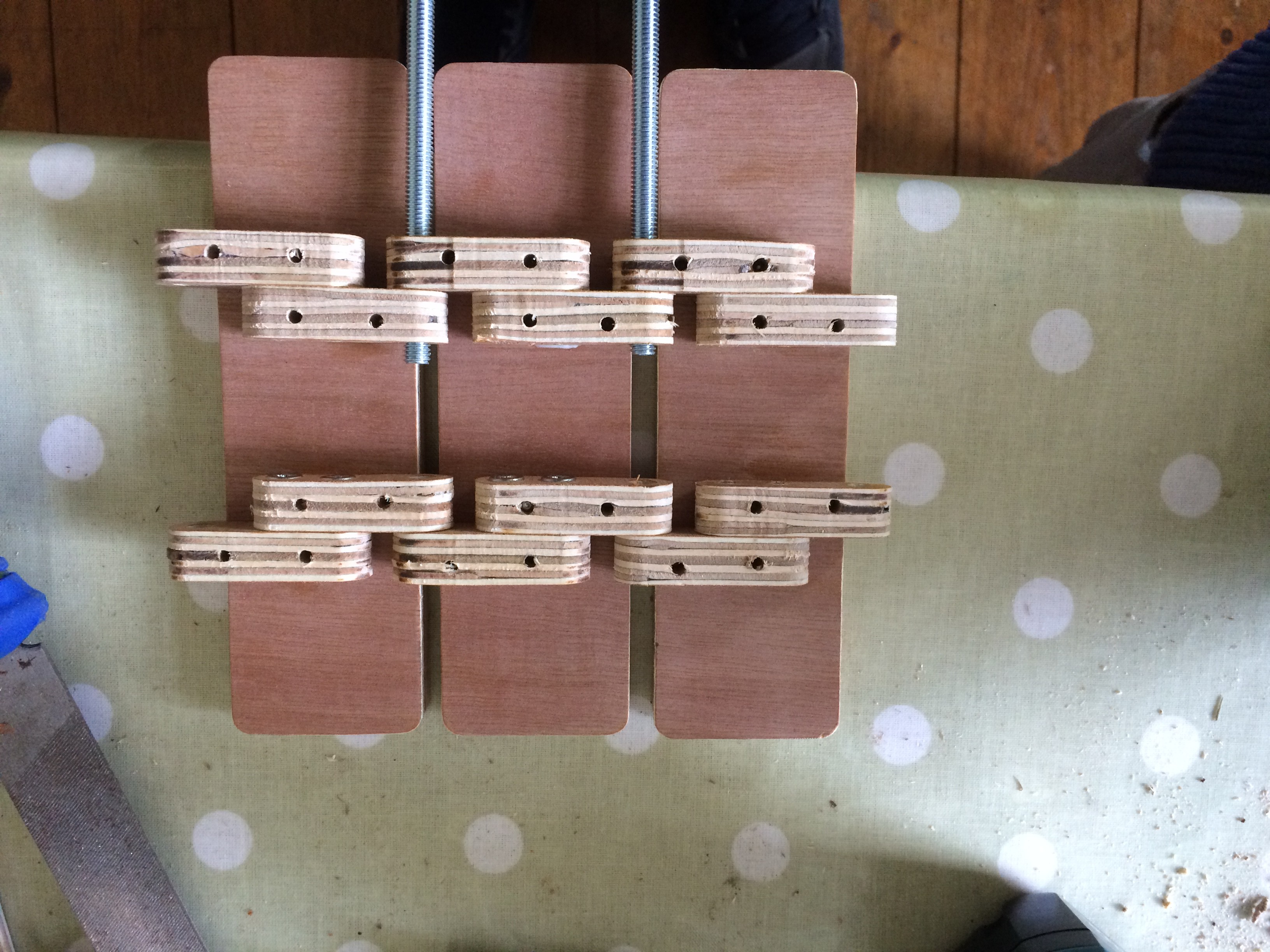
6mm coach bolts to pivot the links and engage with the drive wheel. The heads where later cut off and replaced with nylock nuts.
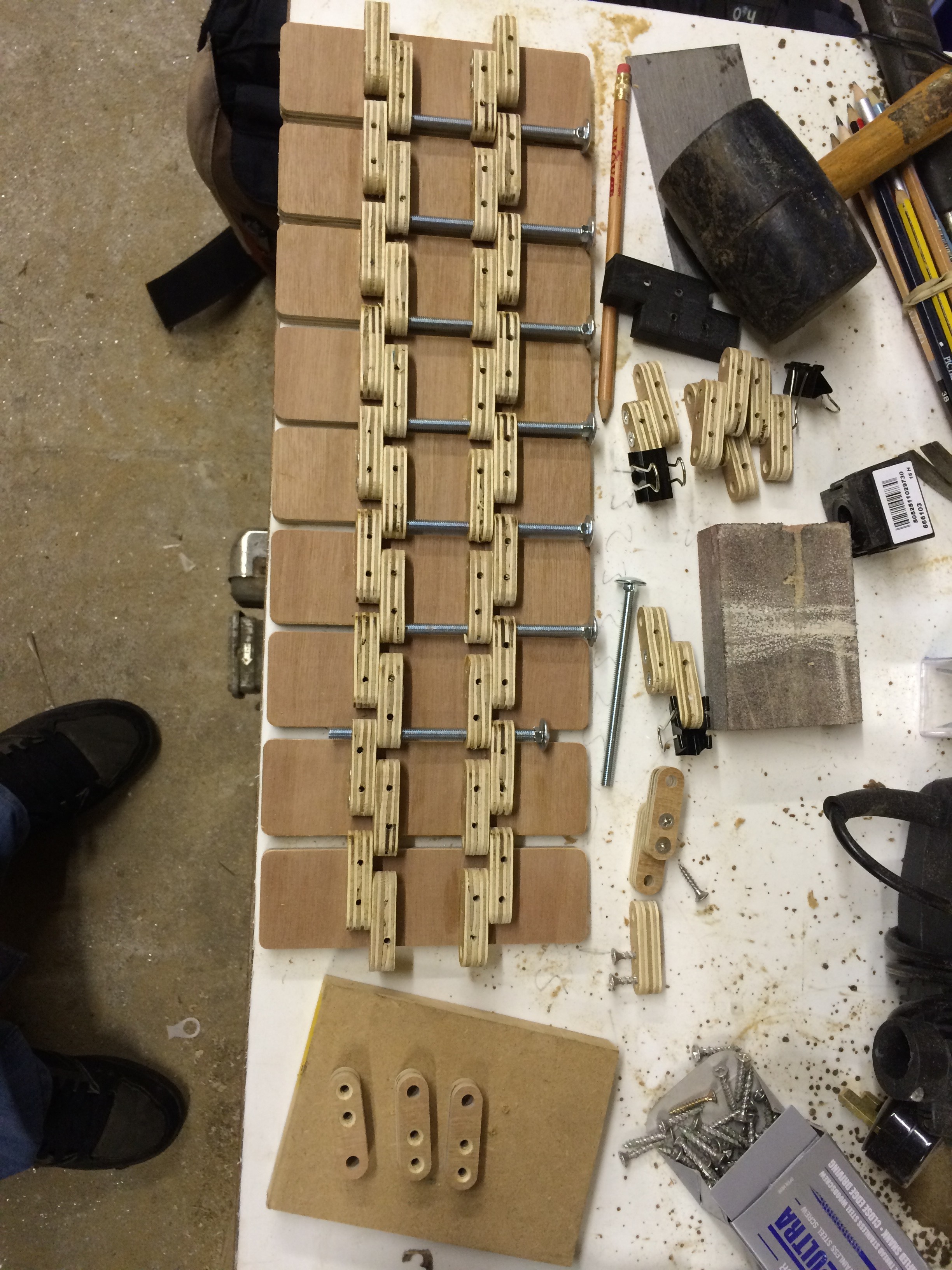
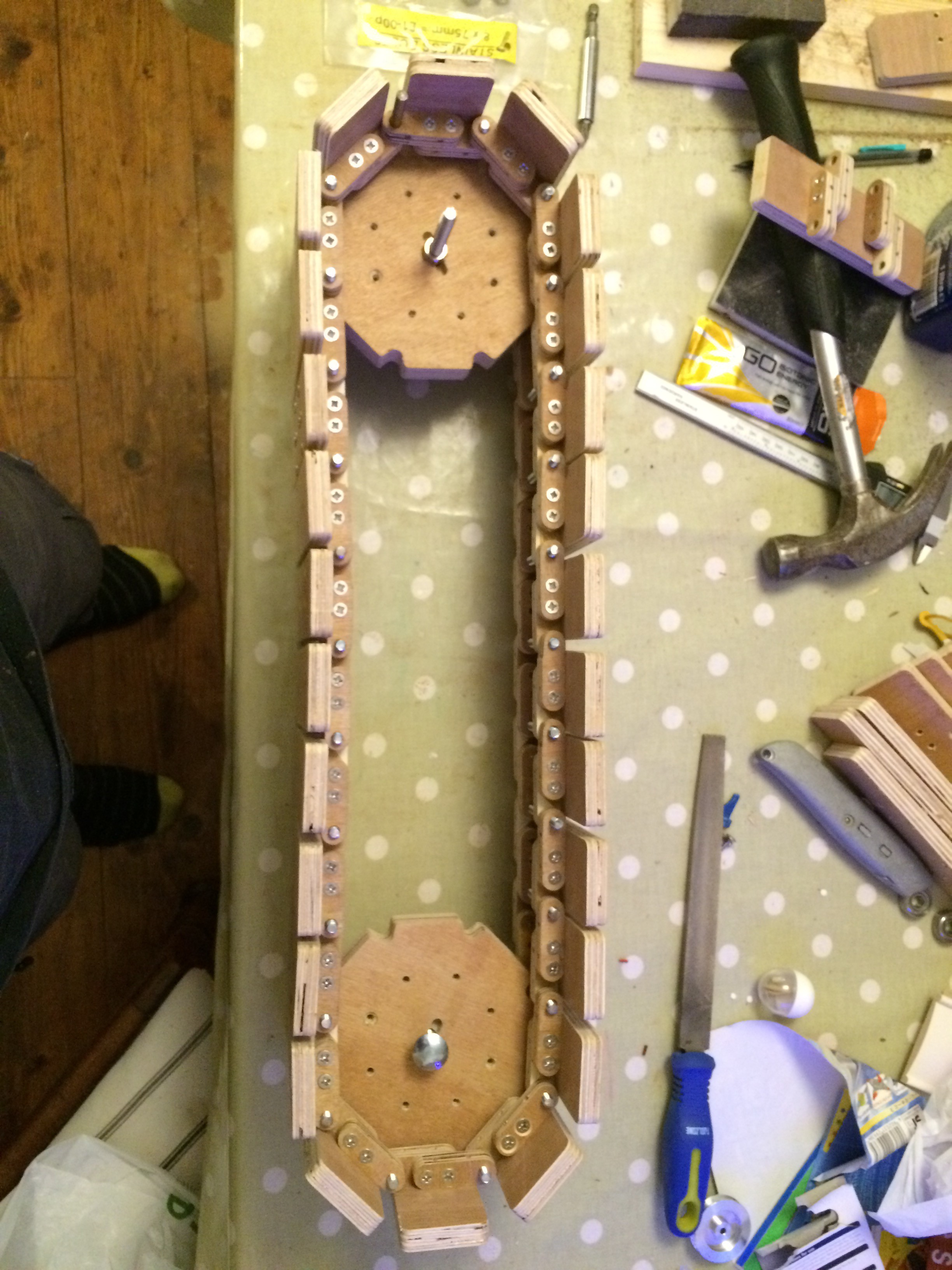
The picture above shows the very first iteration which worked well for a bit but the links were very heavy with the many many screws helping to hold them together. Also the quality of the ply used was not good. This resulted in the links breaking under strain. More on that later...
The picture below is of the drill jig for the chain links to mount the track paddles. I soon discovered that all the screws where increasing the weight and each Paddle only really needed 2...
Read more » Alex Lovegrove







 Maximiliano Palay
 ThunderSqueak
 Sarah Petkus
Really impressive!