Yesterday I soldered the PCB and today I flashed the firmware, previously developed on the experimenter’s board:
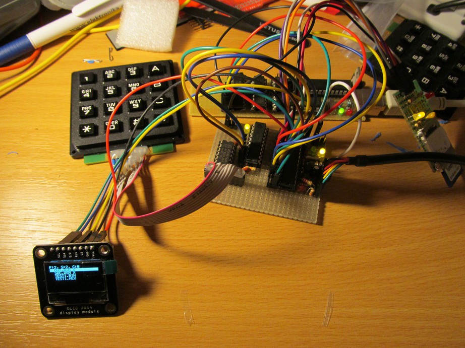
Except of single hardware difference (I ordered PCF8574 instead of PCF8574A - easily to workaround by two #define lines) it ran on the first try.
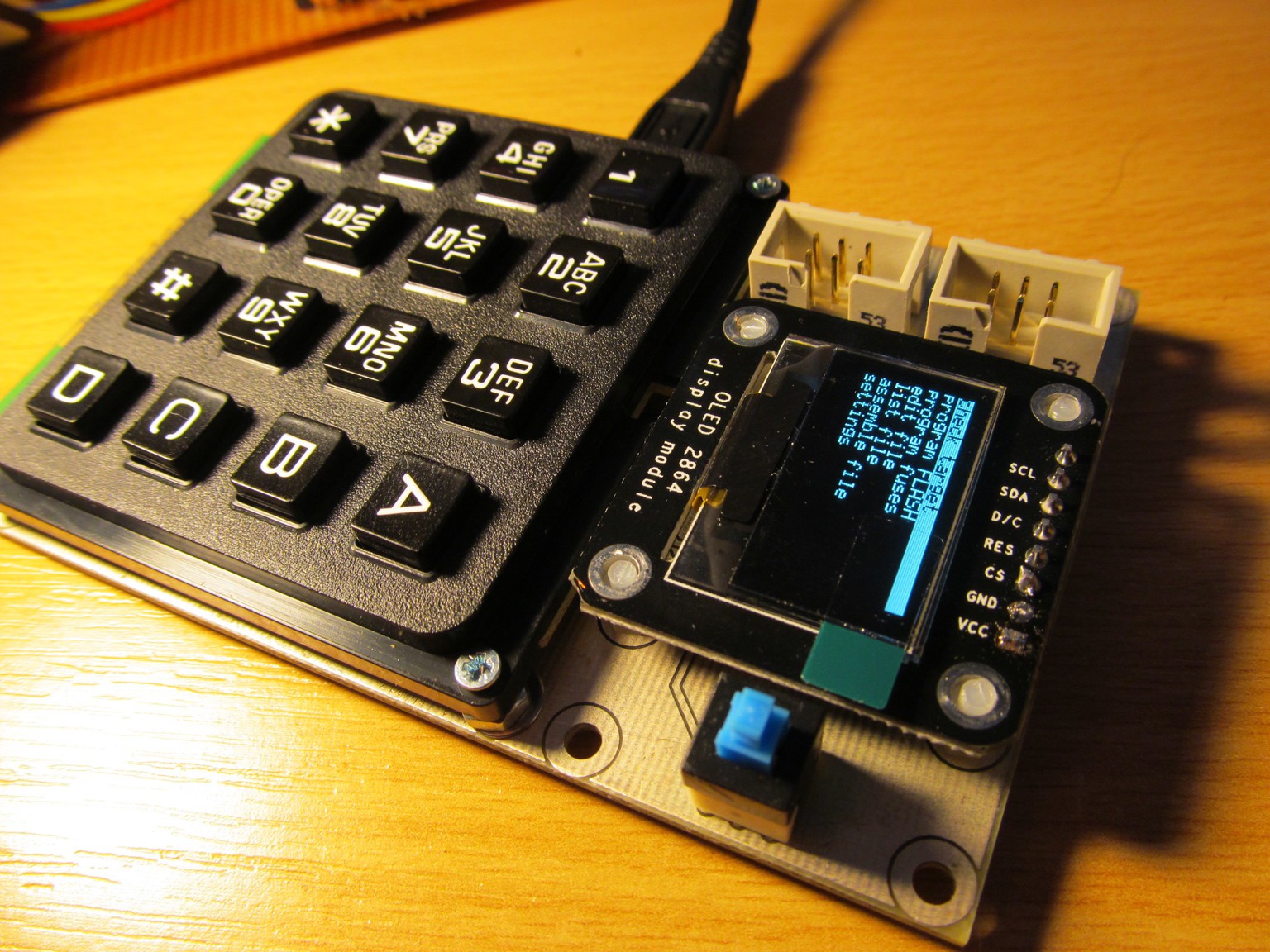
Needless to say, I made a few mistakes on the board during the design (I mentioned missing pull-ups on I2C bus before, did I?). Probably the most serious one is GND and VCC pins swapped for the display. Fortunately, I spotted it before powering the board, though after the display was soldered in place. Probability of releasing the blue smoke from display controller would be quite high if unnoticed. To fix it, I made this ugly workaround:
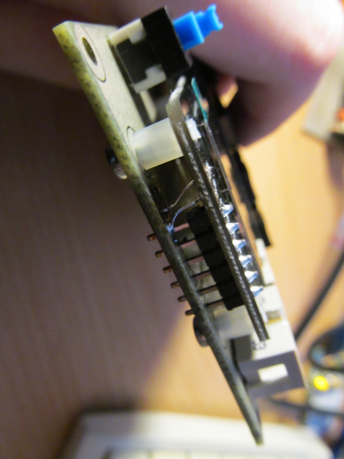
Never mind, I'm adjusting the original design to fix the bugs, so if somebody would ever decide to replicate my design, it will be (hopefully) error-less.
The current firmware allows to program FLASH and fuse bits of target MCU, edit text files on SD card and assemble AVR source files into binary (to be flashed with the on-board programmer) - I plan to film a short video demonstration. It grew pretty huge
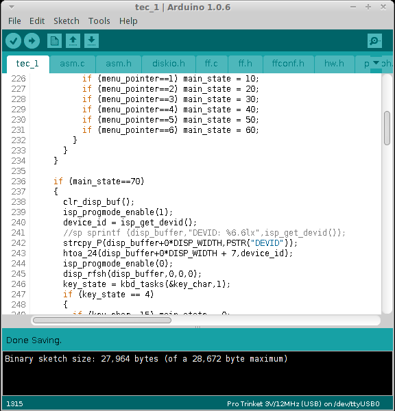
64kB trinket pro would be nice for this project. Currently I'm designing case for it and the first case revision is in the print, as I'm writing this.
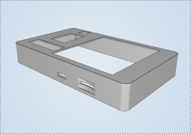
It has round corners, lawsuit, anyone?
 jaromir.sukuba
Discussions
Become a Hackaday.io Member
Create an account to leave a comment. Already have an account? Log In.