-
PCB design
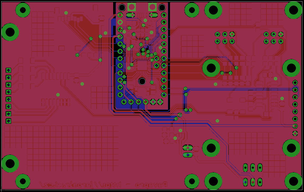
12/21/2014 at 10:58 • 0 commentsMy plan is to design PCB for Pavapro, to have it more compact and elegant, though one can simply hook up a few modules to trinket pro.
![]()
The PCB contains even full trinket pro design (though slightly adjusted). If you are brave enough, you can solder the parts for trinket pro (including a bit tricky QFN AVR and tiny resonator). If you don't feel like this is what you want to do, just leave the middle part unpopulated and solder your trinket pro via pin headers. The rest of components are no-thrills SMD parts.
![]()
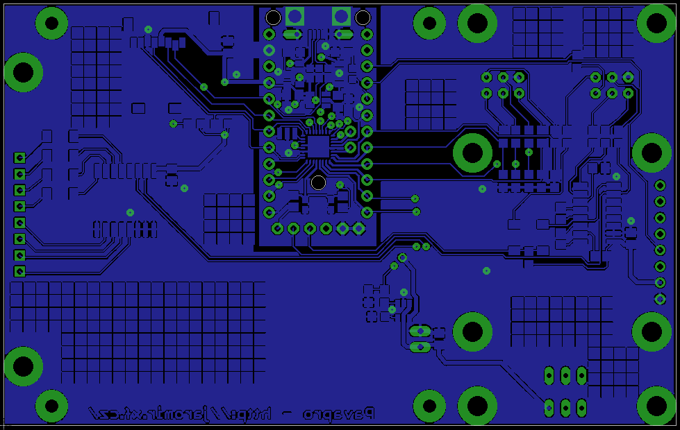
I even left some "breadboard" area on the bottom side to allow future modifications and hacking.
For my design, I recycled the original design files from adafruit. The original PCB wast designed to meet with the particular PCB manufacturer rules, but it wasn't very friendly for home manufacturing or cheaper PCB manufacturers, so I had to move a few parts or PCB tracks, so it can be manufactured with 0,15mm/0,15mm track/isolation witdh, 0,5mm drilling, 0,3mm pad size and no capped vias. I sent the design files to fellow hacker to manufacture it, I'm waiting for the result and working on the software in the meantime.
The PCB design for Pavapro, as well as modified trinket design is on my github.
-
Target AVR connected
12/18/2014 at 16:17 • 0 commentsI dig deeply into programming algorithm of ATtiny2313 and it wasn't that hard. Basically, you need to pull the RST pin down (so the user code doesn't run) and enter command to invoke the programming mode. Then you can issue any other command - to read, erase or write FLASH. In fact, all commands are simple 4-byte SPI transactions.
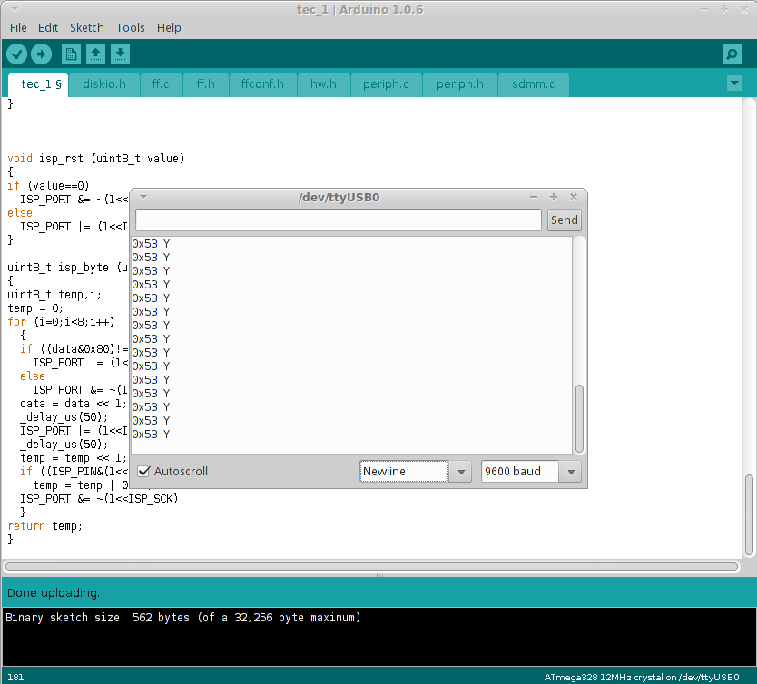
For now I wrote simple programs to exercise the AVR ISP interface and enter programming mode
![]()
Here you can see succesfully returned "Enter programming mode" command; and the same thing on logic analyser
![]()
Notice the 0x53 on MISO line - it is alive!
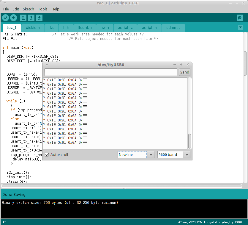
Now I can read out the device ID, for example.
![]()
Great! Now I'm going to implement read, erase and write commands; then I can couple it with SD card read/write functions and FLASH programmer part of Pavapro should get closer to reality.
-
Peripherals up and running
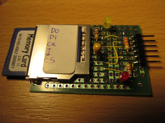
12/15/2014 at 19:34 • 0 commentsLast week I made small breakout board for SD card
and downloaded great fatfs by elm-chan. Make it run was only question of few minutes (did I mention I'm writing the software in plain C, instead of C/C++ mixture as usual for Arduino?), involving witing the SD adaptor to main board and rewriting a few hardware dependant bits. For now I decided to stick with bitbanged SPI for SD card (download example projects and look for avr_foolproof directory) as only few (tens) kilobytes will be read/written from time to time, so it's going to be fine, probably. I haven't done any speed testing, but I expect something in order of few dozens of kilobytes per second.
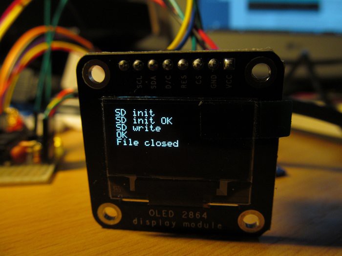
I wrote a piece of code to excercise the SD card (writing short file into root directory) and display status:
Great! So both display and SD card work, consuming some 12kB of FLASH.
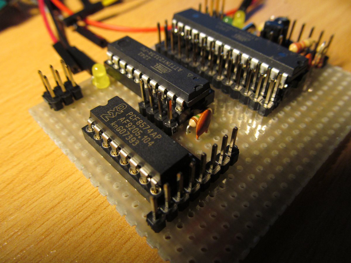
Now I need to add keyboard and sire some target AVR! Because there will not be enough of IO lines, I opted to use I2C expander PCF8574A (because I had a few in my junkbox - I think of using another I2C IO expander in final hardware) on shared bus with OLED display - this way I can connect 4x4 keyaboard with no additional IO lines, compared to 8 lines consumed by classical matrix design.
You can see PCF8574A in front, with 8pin pinheader for keyboard and ATtiny2313 in middle, serving as first guinea pig for ISP experiments.
In following days I'm going to try to make ISP contact of ATmega328 with ATtiny2313, it doesn't look very complicated, after quick skimming through ATtiny2313 datasheet.
-
SPI display is actually I2C or how important is to RTFM
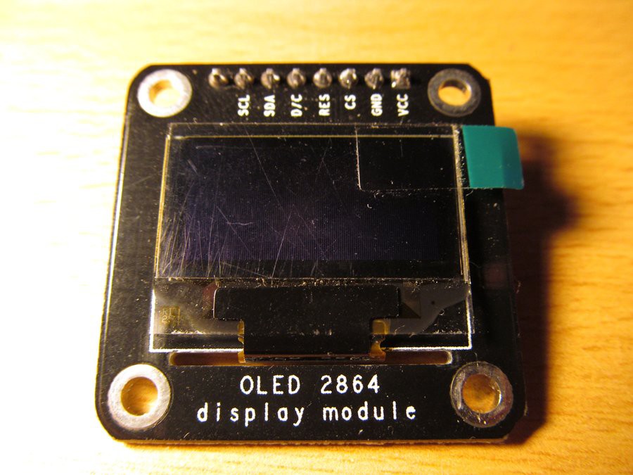
12/08/2014 at 23:27 • 0 commentsSomewhere in corner of my junkbox I found this beautiful OLED display.
"Great display for Pavapro", I thought to myself.
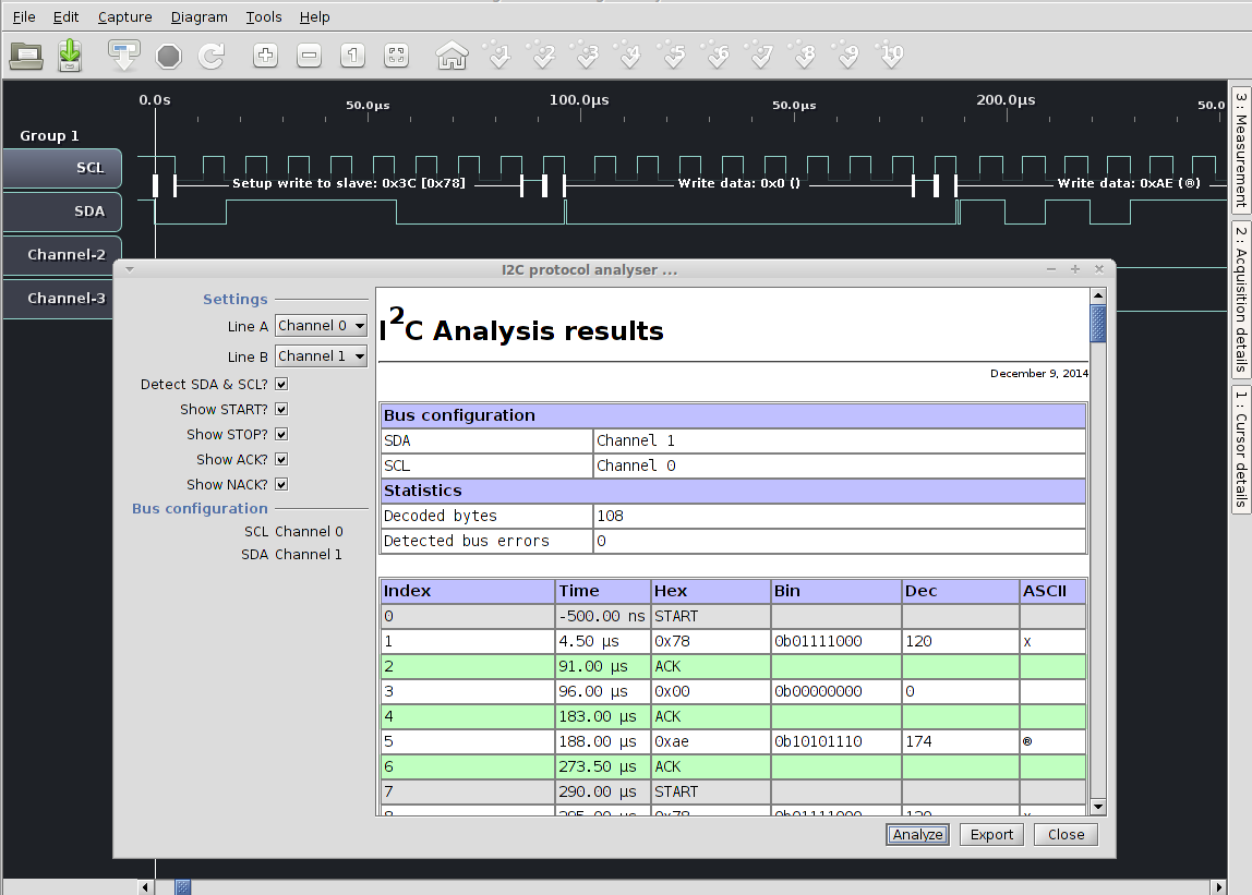
Nothing could be easier than wiring this tiny OLED with absolutely classic SSD1306 driver, apparently in SPI mode - look at the signals, D/C, CS, plus clock and data. I downloaded datsheet of driver and started writing simple driver library. I had experience with the display in I2C mode and already knew it is not that hard. I wrote all the code, with software SPI implementation and everything was great except of the fact the display was completely blank. Logic analyser (this with this software, great multiplatform combo) showed no problems with SPI code, initialization ran as expected, but display was not amused at all.
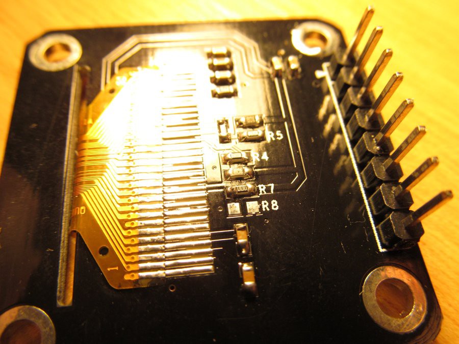
After one evening full of adjusting parameters, changing SPI modes and pulling my hair I remembered I ordered I2C display, not SPI one! I flipped the display board and looked at tje OLED panel pinout. 30-pin 128x64 OLED, this seems to be jellybean part, like this one http://www.adafruit.com/datasheets/UG-2864HSWEG01.pdf. The pin 11 is interesting - it is BS1 pin, along with BS0 and BS2 allows to change the way the display talks to your MCU (https://www.adafruit.com/datasheets/SSD1306.pdf ). In this case only BS1 is interesting, as others are hardwired to SPI/i2C interface and this BS1 does the selection. And this is how it looks on the other side:
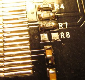
Can you see that?
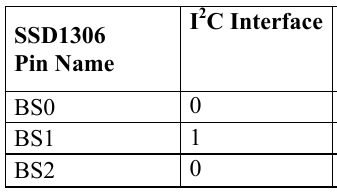
Look at resistor R7 - it is zero value resistor (jumper), connecting pin 11 with thick line on right - it is VDD supply. You can see also unpopulated R8, allowing stripping the pin 11 to ground. So, pin 11 is at logic 1 and looking into datasheet says (page 14, table 7-1) says it is...
...I2C interface.![]()
Well, I reworked my code to use I2C interface and it works, as expected. By the way, I love my logical analyser
![]()
Oh yes, I almost forgot: I could save a lot of debugging by reading the frikkin' manual. Look here (leading to wiki):
OLED display module supports IIC or SPI communication with default as IIC. If you want to use SPI communication, following settings will be needed: Remove resistors on R3, R4, R5, and R7, and weld a 0R resistor on R8.
Ouch.
![]()
-
How I made my 12MHz Arduino
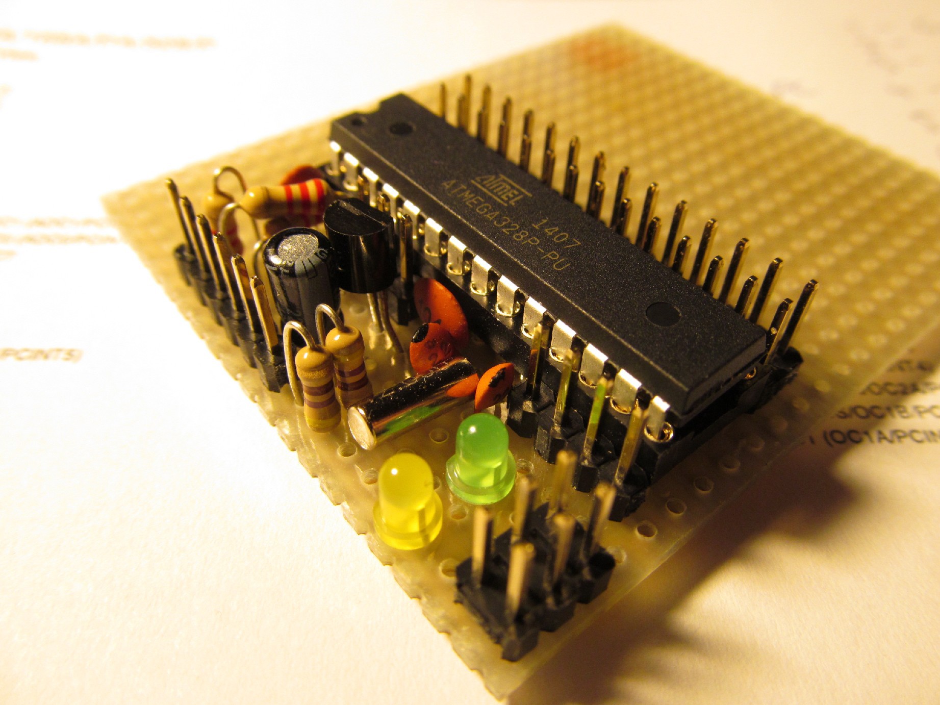
12/03/2014 at 16:04 • 0 commentsMy 3V trinkets are on the way, but I want to start doing something in the meantime, so I decided to make my own temporary Arduino solution - simple arduino on a protoboard.
Actually, there is nothing special about it. Just atmega328p with 12MHz crystal and decoupling capacitors, plus 3,3V regulator (LE33) and serial header. Add two LEDs, some pinheaders and here you go, 12MHz Arduino.
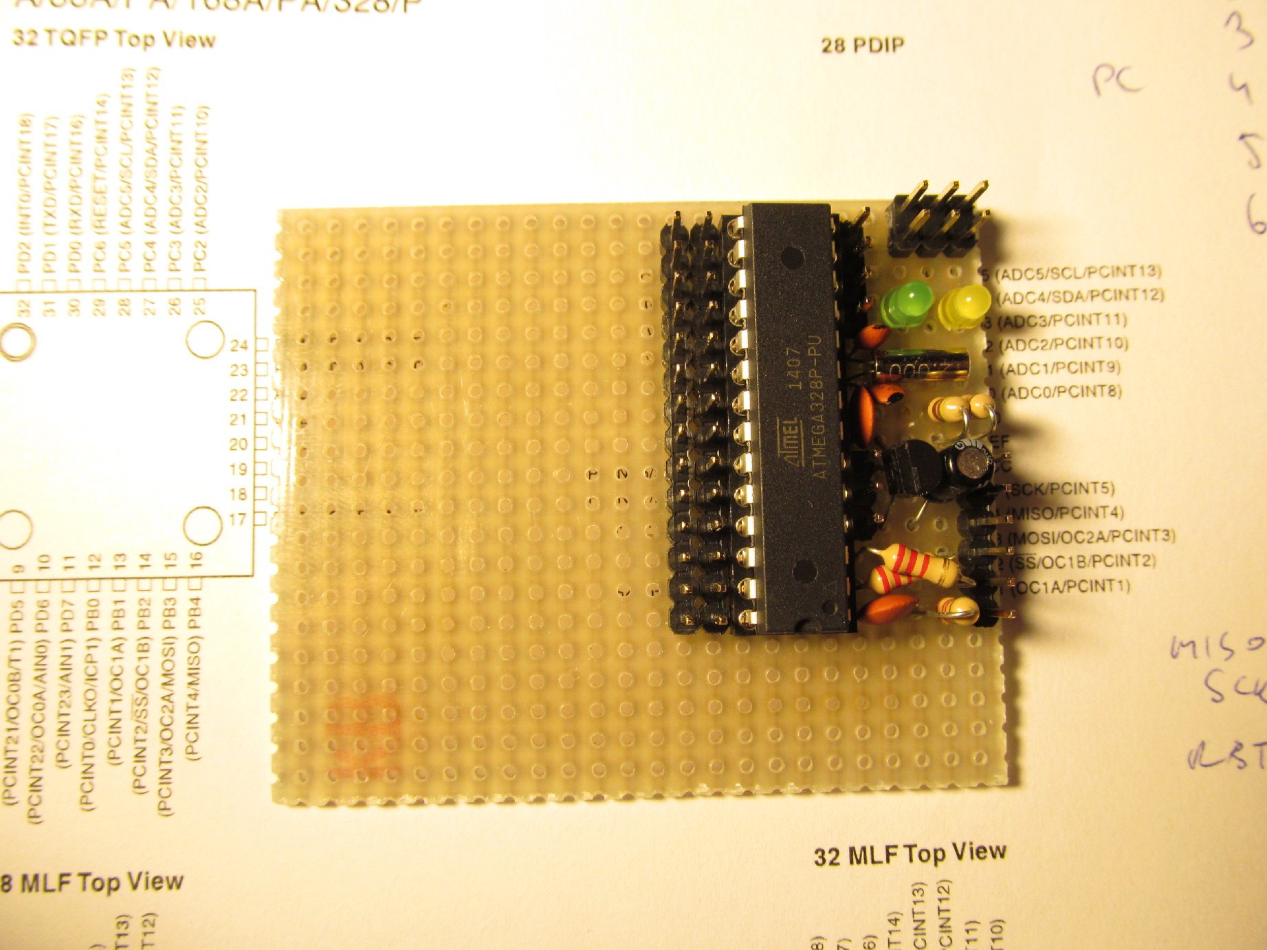
I have no schematics for this, just printed the pinouts of the parts and started soldering on a piece of protoboard.
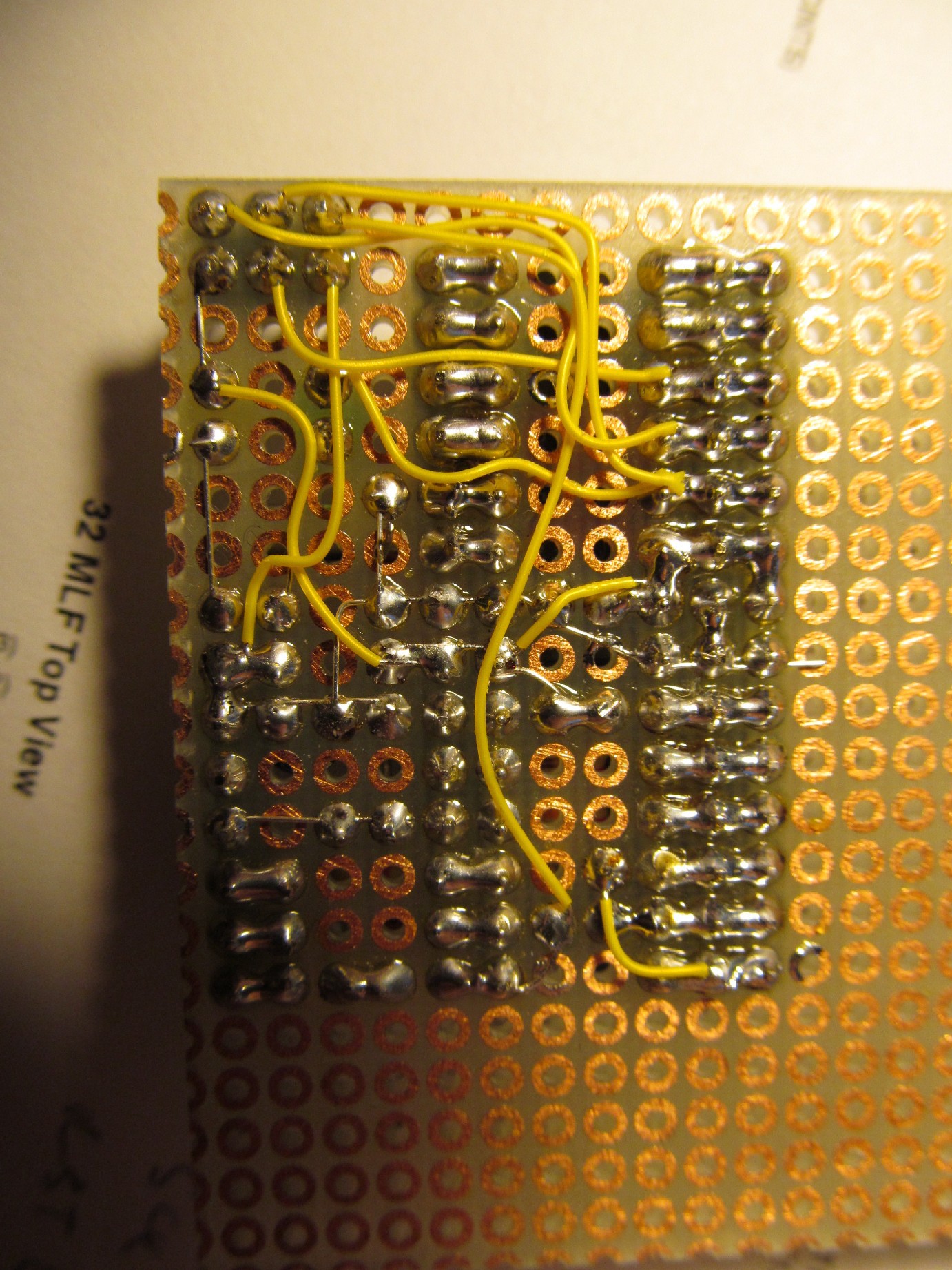
Bottom view:
I spared some space for additional components
The actual arduino hardware takes approximately 3x4cm, including pinheaders. Not bad.
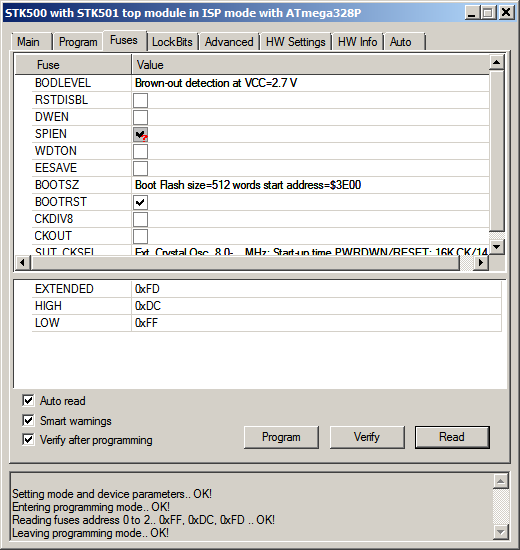
I had a bit of problem finding correct bootloader/fuses settings mix. This website helped me http://ceptimus.co.uk/?p=102 a lot, but there were a bit of head scratching. Finally I settled down with loader and fuses settings (different from what described on ceptimus site) as described here https://github.com/jaromir-sukuba/pavapro/tree/master/test_fw
Fuses as seen in AVRstudio 4![]()
Honestly I have no idea why sugessted fuses settings did work for author and didn't work for me (It threw verification errors and no actual data were written). I tried to read back the bootloader from AVR to found it starts at 0x7C00 (the address where FF region ends)
![]()
Aha! So the boot vector has to be at 0x3E00 (0x7C00 shifted one position right, because single AVR program word is two byte long).
Now I can load basic blink sketch and it blinks! Great, development ca start.![]()
Whew.
-
First thoughts
12/01/2014 at 22:15 • 0 commentsMy idea is to build at least three variants of Pavapro.
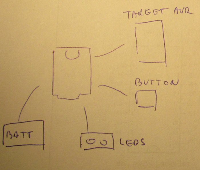
1) First is absolutely barebones minimal programmer - two status LEDs (ready, programming OK), single start button and direct connection to target AVR.
Just hook it on and push the button. Simple enough for rewriting arduino bootloader, for example. Though internal EEPROM of Trinket pro is nothing more than 2kB, it shoulld be enough for classic optiboot bootloader or your favourite blink a LED program.
(the box in the middle is trinket pro, sorry for missing legend)
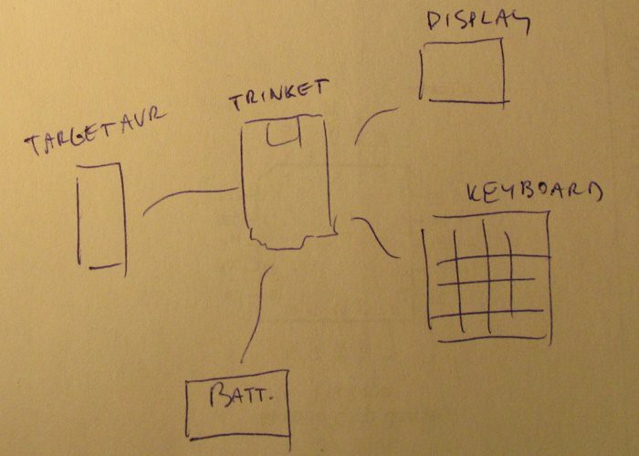
2) Full blown version will contain display too, to show the programming status, so LEDs will be omitted. Keyboard addition will allow to edit the AVR programs "on board" or play snake, who knows by now.
External memory could be I2C EEPROM or SD card, I'm unsure by now. SD card would require SPI bus sharing with target AVR, so the I2C EEPROM looks more reasonable.
Display will be classic Nokia 5110 type or tiny I2C OLED. I'm going to analyse the display and memory possibilities further.
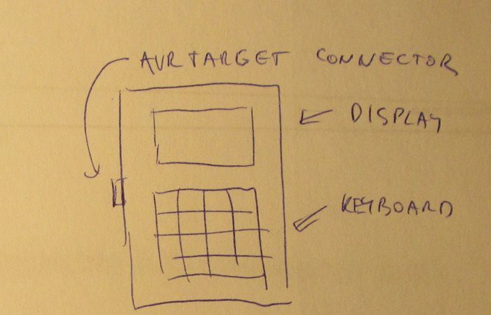
3) This is simply repacked 2) into nice package. But we all know that final look is what matters, that's reason for separate paragraph and even this beautiful visualisation.
My aim is to write software that with a few #define lines user could customize it for his needs (and cover all the options or something in between).
Pavapro - portable AVR programmer
Pavapro is tiny programmer you can bring anywhere. You can load binary file into it and bring/use it as you wish. And a bit more than that.
 jaromir.sukuba