Trinket Timer
A small pocket timer for anything. Reminders, countdowns, etc. Great for kids when you don't want to put a $200 iPod in their hands.
A small pocket timer for anything. Reminders, countdowns, etc. Great for kids when you don't want to put a $200 iPod in their hands.
To make the experience fit your profile, pick a username and tell us what interests you.
We found and based on your interests.
So, altoids tins. Staple of Makers everywhere. Electrically conductive metal boxes of shorts, sparks, and letting the magic blue smoke out.
But there is a solution. I ran across this instructable on how to make your altoids tine electrically inert. Really awesome solution, but I have yet to see how well it wears. Basically, there is a spray on plastic coating you can get from your local big-box store that will cure on the internal surfaces of your tins, and render them safe(r) for electronics.
Here's my basic procedure.
First, I lay out the design for my lid backwards, so that when I flip it over, it is the right way. Actually, I didn't the first time. Don't do that. That sucks.
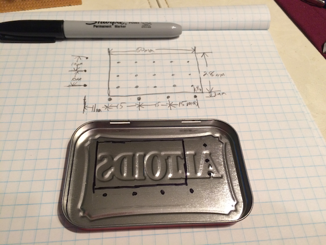
Then, I punch and drill the lid. The big drills in the corners of the black square are where I will use my dremel tool to cutoff in between for the large opening. The punch sets the center of the holes so the drill bit doesn't wander. Nobody likes wandering bits.
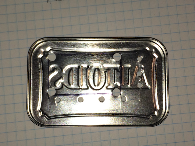
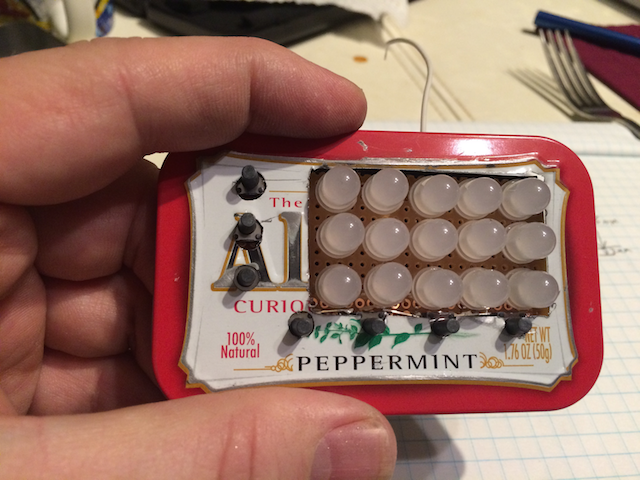
Then, after making sure there aren't any burrs to cut myself on, I attempt to fit the parts into the lid. This fails miserably. Multiple times. After much foul language, sandpaper rework, and re-drilling with larger bits, everything fits perfectly.
Nailed it.
(If you check out the "l" from Altoids, you can plainly see where the sandpaper wore off the paint.)
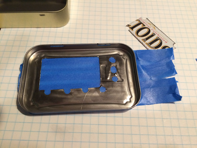
Then, I masked off the outside of the tin with painter's tape, and sprayed it. Note the chunk of the lid sitting behind it.
Once sprayed ( 30 minutes between coats, 3-4 coats, 4 hours to cure), this is what mine looks like. Because I like blue. A lot. Boy, from this angle, you can really see my oval holes. Note to self: destroy this picture before posting. Also, through no fault of my own, and in no way the result of sub-standard spraying process, or really really cold temperatures in my garage, or the fact that it was late at night, and I had either too much or too little caffeine, or anything I may or may not have done at all, there are bubbles in the corner of that one side of the lid. I'll live, and so will you.
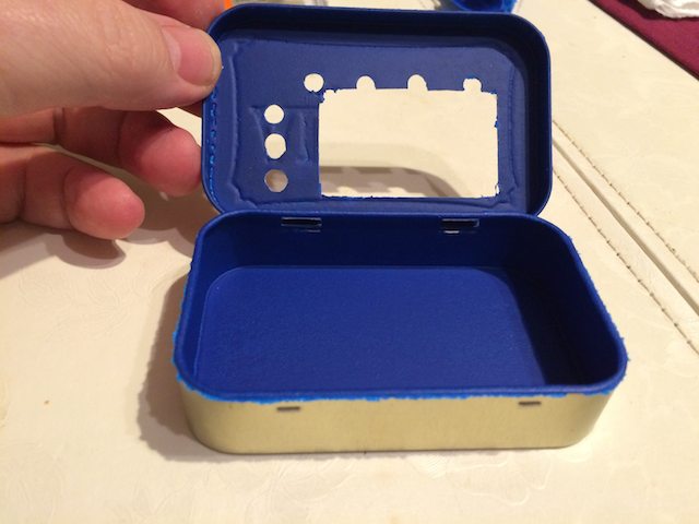
In all, this technique leaves a semi-stretchy rubbery plastic coating on the surface of the tin. Seems pretty thick, and has a very nice matte finish. For what it is worth, I really like the way it came out for my first time.
One thing I think I will do differently next time is remove the masking tape before the thing fully cures. Would have made less work in the clean up phase.
So this was my first version:
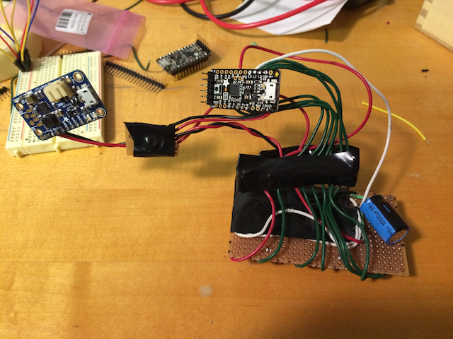
Lots of big, not-very-bendy wire. And perfboard junctions. Then I tried to put it into my Altoids box (my chosen form-factor). Well that just sucked. Here's what I've cut it down to so far:
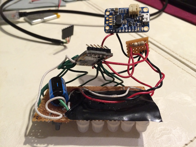
I took out the perfboard that connected the LED matrix to the trinket and the booster, then merged what I had left onto one much smaller perfboard. The single resistor seen on the perfboard *was* going to be the one pull-down resistor I needed, until some pesky reality busted in on me. I may be able to use it, but reversing the polarity and crossing the streams or something.
But at least this fits into an Altoids box. Well, it does if I don't actually *need* a battery. Hmm.
Also, note the bent pins on the trinket serial connector. That's an essential part of of the "fits-in-an-altoids-box but still debugs" technique. You may think that's a bad thing in a conductive metal enclosure, but I've got something for that in the next installment.
I haven't been able to put in as much work as I wanted to on this project, but I'm not stopping now.
The most recent snag is in the buttons. I knew I might have problems with floating values, the wires connected to the arduino might have odd values because they didn't connect to anything, and essentially acted like antennas. The traditional solution to this problem is a pull-up or pull-down resistor, to set that voltage to a known value, which I was hoping to not need.
Needless to say, the laws of physics did their level best to ignore my pleas and refused to bend for me. Pull-up/down resistors here we come.
I *was* trying to supply voltage to one side of the button, reading it on the other side. I wanted to do this so that the high side could trigger an interrupt and my interrupt service routine (ISR) could then read the button values for me. This was to keep from polling the buttons and basically burning power for no reason.
The ATMega chip used in the Arduino has internal pull-up resistors to set inputs to a HIGH state. But that's backwards from how the circuit is built. Oh well, back to the drawing board.
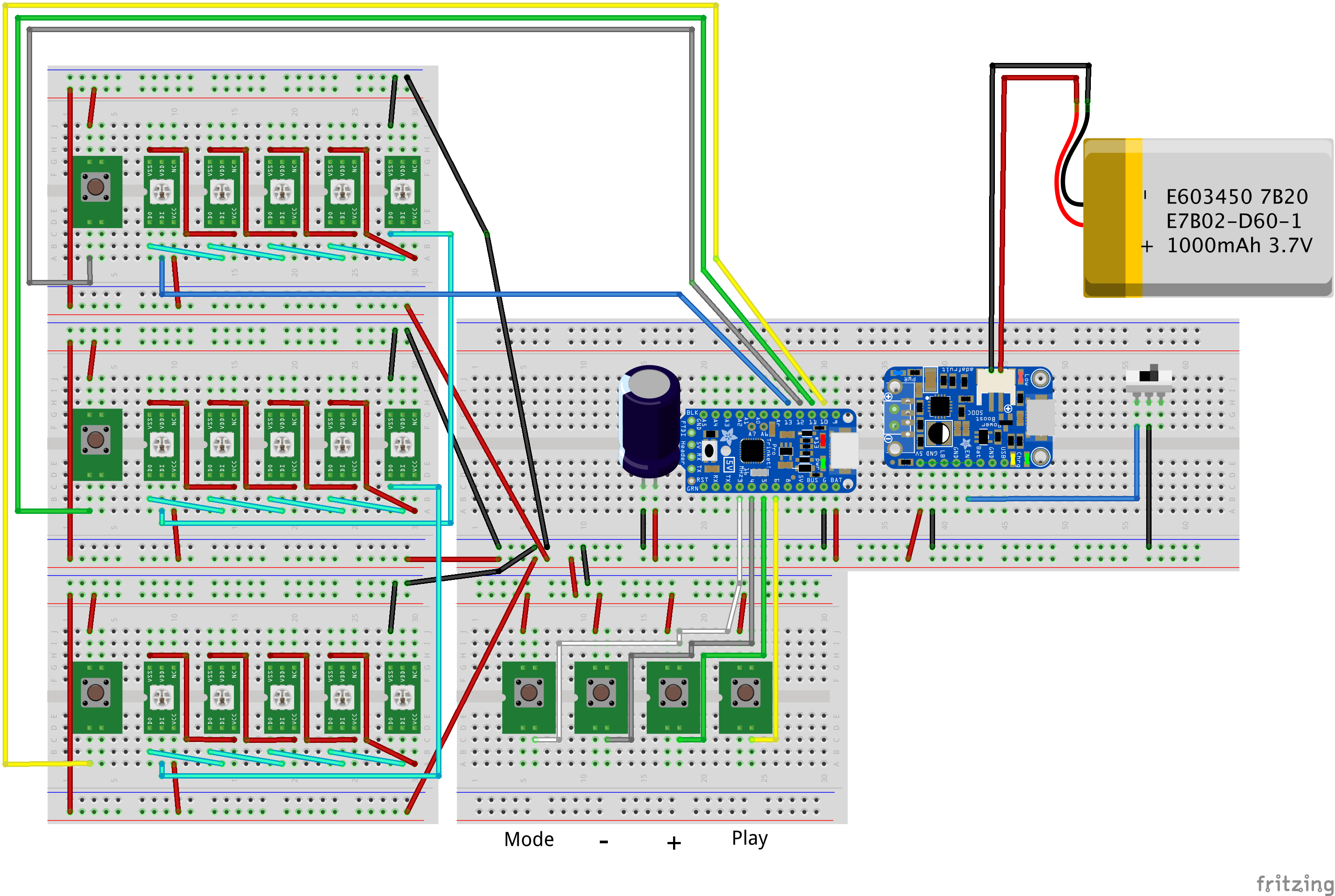
I noticed when I was posting that last log that I had an image of a matrix wired up, but the Fritzing diagram didn't match. I *had* updated the Fritzing, but hadn't posted the log. This image should be closer to what I actually soldered:
And here's a picture of my (broken) perfboard with buttons on it, as it will be mounted on the LED matrix:
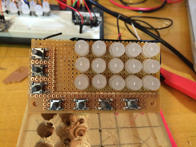
I didn't realize the tac switches were surface mount. Oh well, just makes it a bit trickier.
Been a while since logging, because Christmas.
Anyway, I got the full matrix wired up and settled. I'm writing code now, but here's a picture of how I'm wiring everything up.
On the left is an image of the back of the matrix, but if you think that looks confusing, try soldering it! So I drew some hints onto the image on the right to give an idea of what's actually going on.
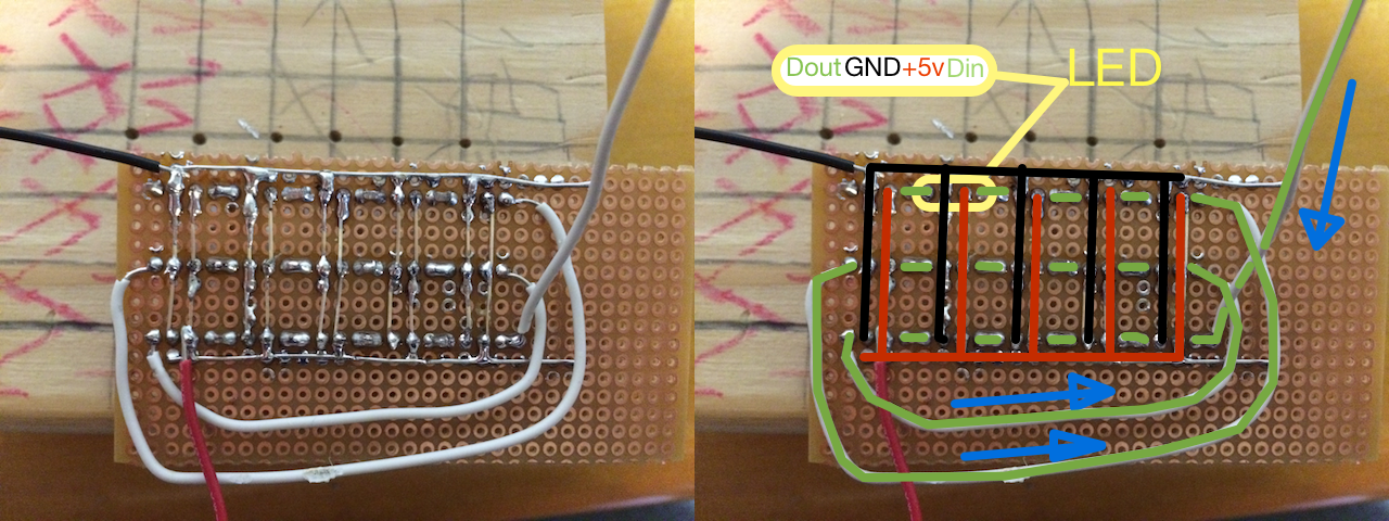
There are basically three "busses" at work here. The red bus is carrying +5v, the black bus is ground/earth, and the green bus is the data bus. The way the NeoPixels work is by daisy chaining the LEDs together via the Data In/Out pins, which are the outer pins. Each LED takes power and ground for itself. Data comes in from the green wire that goes off-screen to the upper right, and goes right-to-left through the bottom row of LEDs, where it comes out and is brough back to the right side and put into the second row of LEDs, and so on for the third row.
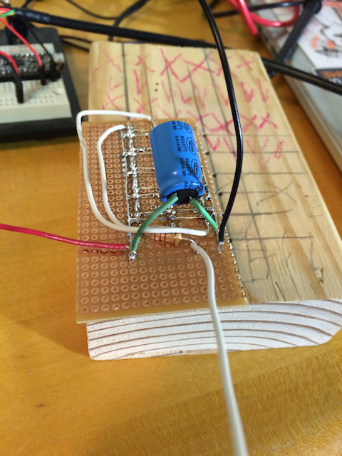
The next picture shows the finalized matrix, with a capacitor across the power and ground busses to protect the LEDs from inrush current when the circuit is first powered up, and a small resistor inline with the incoming data line to protect the microcontroller in the first LED (This forced me to move the incoming data line to be before the resistor). I simply *have* to find a smaller cap!
I need to solder a bunch of LEDs for this project, and I'd like them to be a fairly even, so I made a jig to help out. Here's a video for information:
Spent some time really laying things out in Fritzing. Here's the diagram:
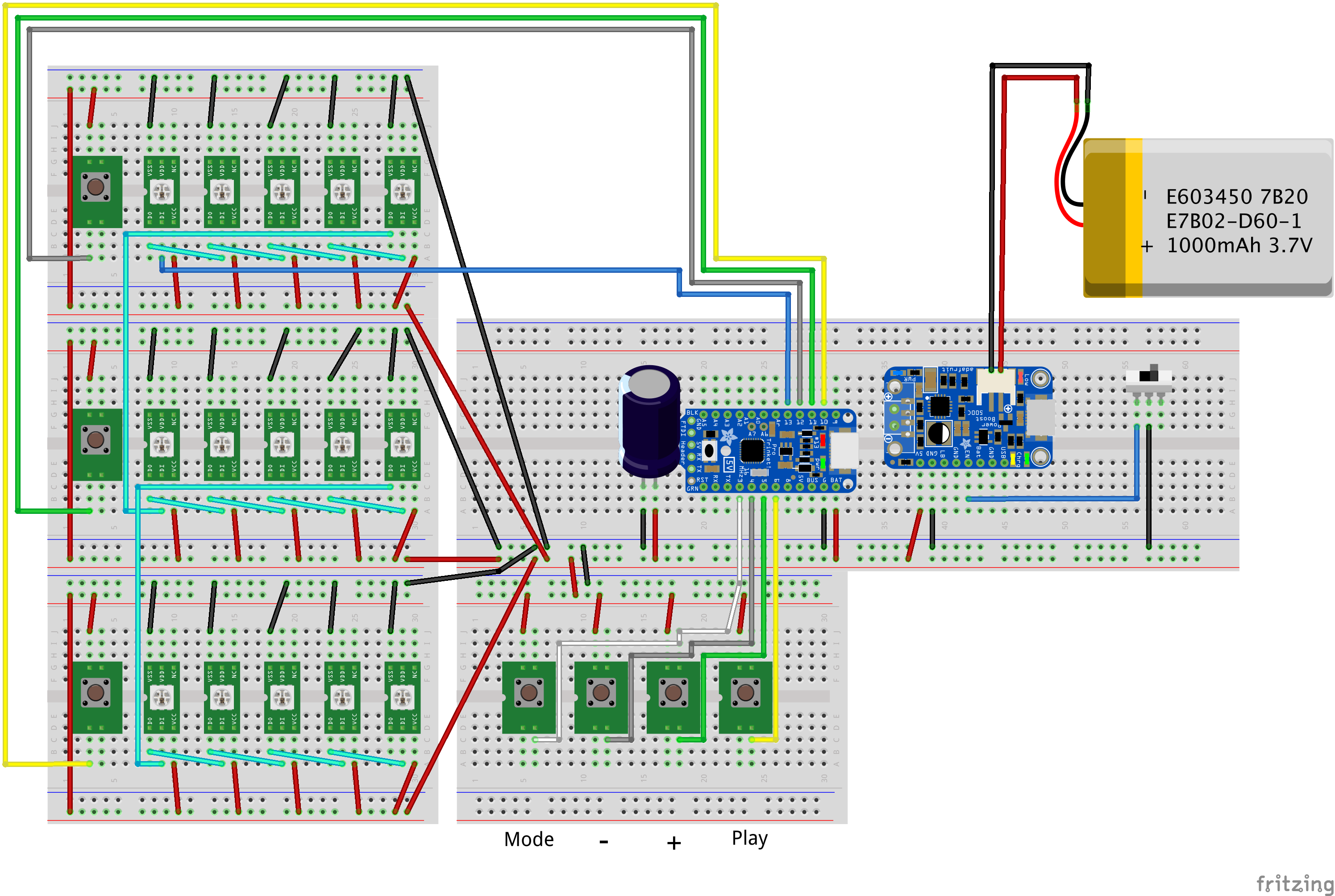
I didn't label the tac switches on the LED rows, but they are for row select. The Big cap in the middle next to the Trinket Pro is a 1000uF, 35v cap. The docs on the NeoPixels recommend a "large" capacitor across the power lines before the first NeoPixel, to protect the NeoPixels against inrush current when the circuit powers up. The docs recommend 1000uF, 6.3V or bigger, and I had the 35v laying around. Massive overkill, I know.
The switch on the far right drops the ENable line on the booster/charger to GND, cutting it off.
You'll note there is only one data line going into the LED array. I'm debating whether or not to leave it like that, or split each row of LEDs into a separate control line. I don't really *need* to split it out, but it might make my software design easier. Or harder. I
ll have to play with it.
I got a shipment from Adafruit today, my NeoPixels have arrived.
I immediately set out to gauge the actual power consumption in my circuit, so I setup a strip of 10 LEDs on a breadboard, and ran a demo sketch from the Adafruit NeoPixel library. Like Stryker295 said, these things are crazy bright, even the so-called "diffuse" ones. Check it out:
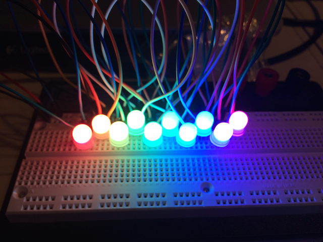
As for power consumption, the worst case is 60mA/LED, but I found a "rule of thumb" rating in another part of the docs. They claim 20mA/LED is a good place to start, YMMV. Putting them in my circuit, and using a current meter on my USB port, 5 LEDs at the maximum brightness ran around 100mA, with 10 LEDs kicking it up to around 200mA. In my usage, it would appear the 20mA/LED is a fair estimate. With the (at least) 15 LEDs I'll be using, I should hit 300mA in the bright case, with more like 50-100mA most of the time.
I then hooked up the LiPo booster/charger to the circuit instead of the USB cable to see how the battery did with the 200mA draw. There was no change in performance of the circuit, so I think I can live with that.
So far, this project is heavy on conjecture and light on parts, but I'm sharing what I have as I have it.
This is an initial sketch of a layout I was thinking about. There would be an array of 15 RGB LEDs, laid out 3 high by 5 wide. The bottom row would represent one second chunks, the middle row 5 seconds, and the top either 15 or 25 seconds.
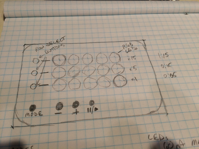
You would "set" the time by incrementing the number of lit up LEDs with the +/- buttons and the row selector buttons, then just press play. For instance, if you didn't select a row using a row select button, it would default to the bottom, 'single seconds' row. If you advance past 5 seconds, the first LED on the second row would light up, indicating 5 seconds. If you wanted to jump straight to 15/25 seconds in the top row, just use the row select and start advancing.
About the 15/25 second top row. I haven't decided what the top row would mean yet. 15 seconds seems easier to me to do math on (3 x 15 seconds is 45 seconds, etc) but 25 seconds would be more consistent with the bottom two rows, as you hit 5 seconds in the bottom row, the first LED in the middle row lights up, so hitting 25 seconds in the middle row would make the first LED in the top row light up.
The "Mode" button would shift times from seconds to minutes so you could time longer things? I was thinking that I might use colors to represent that shift. Red == seconds, Green == minutes, etc.
Maybe. Or maybe not, what do you think?
So I originally wanted to go heavy on some RGB LEDs on the timer instead of some kind of LCD display (character or graphical). I wanted it to be functional, but have some kind of colorful fun factor. I was worried about the power requirements of a bunch of LEDs, and for good reason.
I've been looking into using some 8mm diffuse NeoPixels from Adafruit, but the power rating on them maxes out at 60mA at full brightness. The 15 I wanted to use adds up to 900mA if all are on a full brightness. That's almost twice what I can draw from the LiPo Boost converter I'm using!
Now, I'm probably not going to run all of the LEDs at full brightness at the same time, but I'm probably closer than I'd like to be.
So I have to do something. But I have two options: reduce power drain, or increase power supply. Decisions, decisions.
Create an account to leave a comment. Already have an account? Log In.
Indeed. I'm going to keep it in mind for my probe project, because that's also going to be tightly packed in a tin.
Become a member to follow this project and never miss any updates
Nice tip on insulating the inside of the Altoids tin... I'm going to use that trick someday.