13 December 14
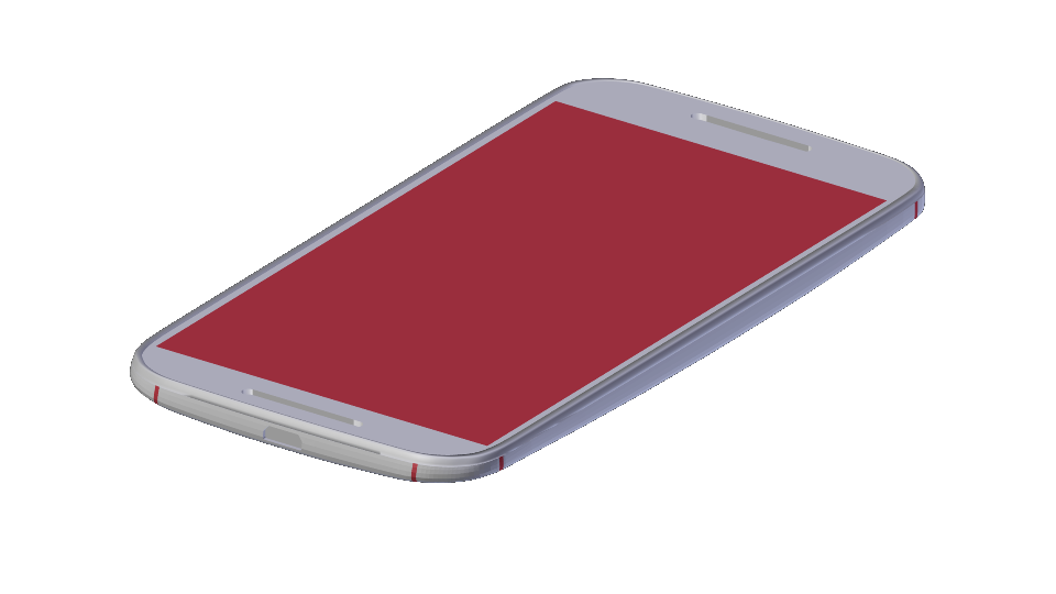
I continue to work on getting the 3D model of the case right. I had finally managed to Boolean my way to a decent 3D shape and went to cut out the phone just to discover that the model wasn't good enough. It is very important to have a manifold mesh when using booleans, and the phone model wasn't even close. I spent some time to make it right and was pretty happy with the result. Now I can subtract this from the case shape I am looking for and it will mold itself around the phone.
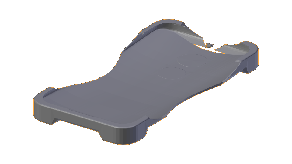 That brings me to my first try at getting the shape I want. I really am happy with the process, but not the result. I think about holding this in my hand, and it doesn't shout "comfort" to me, and I am not entirely pleased with the overall shape, either. I think I will be moving to a shape with 3 feet that will be easier to grip but will still stick to the charging base I have in mind. Stay tuned and I will continue to update this project log with my adventures in making a 3D model of the case with blender.
14 December 14
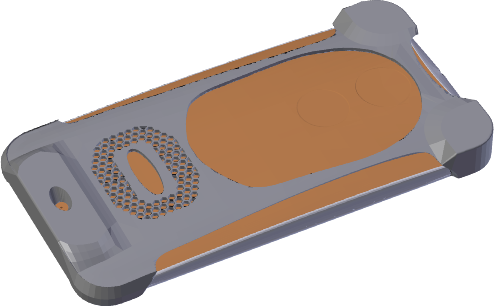
After a significant amount of trial and error, I have finally produced a case shape that I am happy with. The large window and edge pieces will proudly display the custom back on my Moto X+1, while the 3 legs should make gripping easier. A hexagon mesh will reveal the wireless charging coil beneath it. The curve on the back was accomplished with the shrink wrap modifier, so that the back face of the case is a set distance from the phone. I used Boolean operations to remove the sides, top, left and right sides, and all the windows in the back. I also used Boolean operartions to subtract the screen area on top and the actual shape of the phone itself.
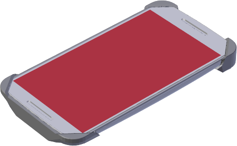
One big change from the first go is the corners are now clipped at angles to allow for 3D printing using bridging and no supports. Ninja Flex does bridge pretty well, but it has to have something to bridge to.
I will have to be careful to make sure that the camera is not covered, though I am sure an Exacto knife would take care of that. The Moto X+1 also has 4 IR sensors near the edges to be wary of.
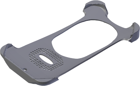
Moving Forward, I will be adding some space at the bottom to connect the USB jack, and will cut out some space for the charging module and the wires that will run to it. For extra support around the USB jack, I will probably have a separate piece that goes around it and molds to the phone. I also need to cut out some space for the washers, before the model of the body is done. Before I do all that, though, I am going to be producing support material for the curved bottom of the case.
15 December 14 - 4 January 15
After getting the shape I wanted above, I added some room for the USB port and charger at the bottom and tried several methods of generating support material. Here, I mostly want to focus on the shaping and modeling techniques I used throughout this process. I will post a separate log about slicing with Slic3r and my various attempts at printing.
I began by generating models of the parts I would be embedding between the case and the phone, including the wires, the receiver module and the USB plug. I decided the best way to fully hide the USB jack would be to have an ABS surround for it that was between the case and the phone. I created the general shape I wanted for that, stretched the bottom of the case around it and used Boolean operations to give me room to insert it later. I then subtracted the parts I had modeled and generated some channels using the shrink wrap modifier.
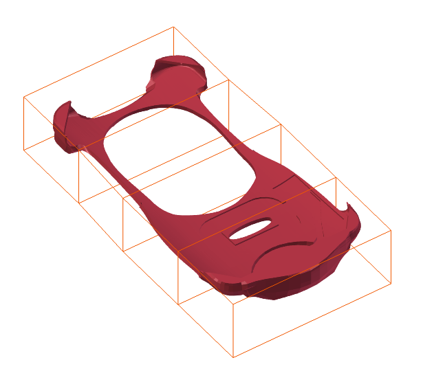
One of my goals is to have the Ninja Flex stretch a little bit when its on the case, so that it stays on well. To accomplish this I initially scaled the top bit (where the headphone jack is) towards the center using Blender's proportional editing tool to keep a continuous scale. This produced fair results on the model but was hard to reproduce. After some later hiccups that require me tweaking the unstretched model, I grew wary of doing this repeatedly and decided a lattice modifier was the way to go. Using the lattice modifier and the lattice shape shown in orange, I was able to easily move the top portion down and shrink it in the middle. A bit. If I want to repeat this at a later point, I just need to reapply the modifier.

To generate the support material, I created I selected a series of line segments that were around the border of the case, copied them, seperated them from the case mesh, and scaled them to a plane. I then filled them and extruded them up to the maximum height I thought I might need support material. The first method I used to keep the support material from being printed in layers above the case was to generate a similarly contoured model by using only the shrink wrap modifier without the Boolean difference modifiers for the open parts applied. I scaled it down a little and subtracted the case model from the support block to get the final shape. To produce a patterned shape on the case, I initially used a grid of hexagons with some space in between them, and subtracted them from the block as well. After my first tries at printing this, I realized that this method was not going to work because of how Slic3r looks at it. After this result, I decided to take a different approach to the support material all together.
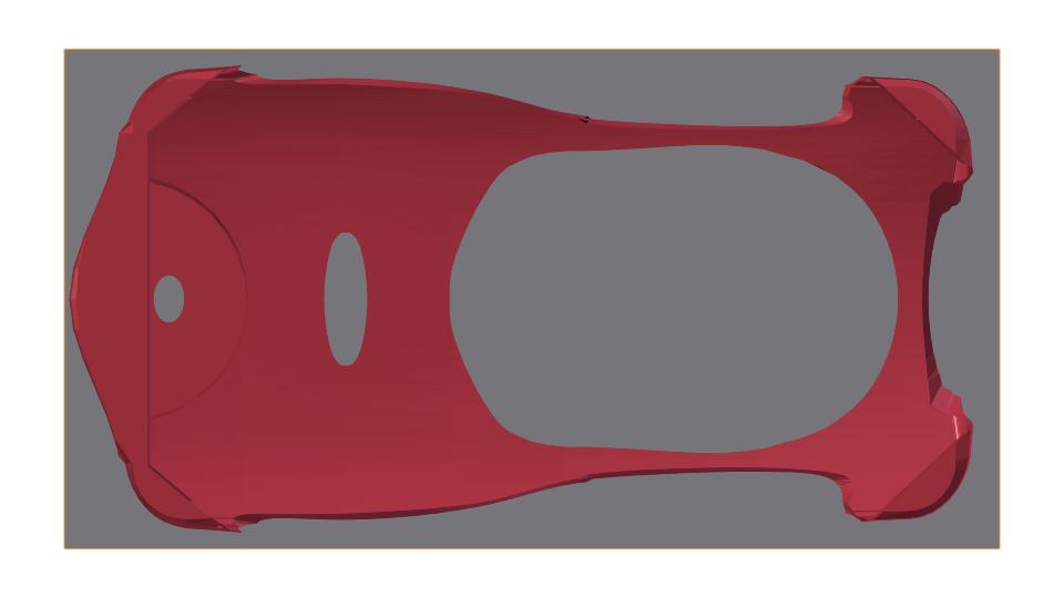
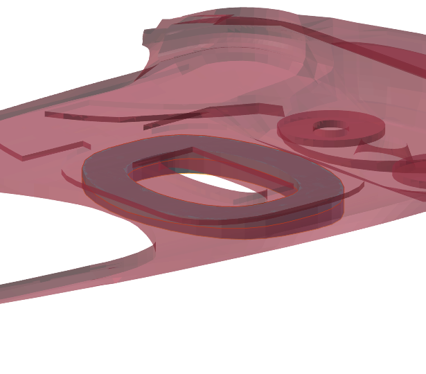 The hexagons that made the original support material problematic also caused problems with the hexagonal windows. To counter this I modeled the locations I wanted the windows and inserted them in the Slic3r. After modeling the window area, I used an intersection Boolean operation between it and the case model and the window area to create a volume that I wanted to be printed with windows in NinjaFlex. To match it for support, I also took a copy and shrink wrapped it so that the top portion of the area was inside the case model, then did a Boolean difference of the case model to produce a shape for Slic3r to print in ABS.
 J. Kha
Discussions
Become a Hackaday.io Member
Create an account to leave a comment. Already have an account? Log In.