 Hacker404
Latest Status Update:
Sunday 24 April -
Project log added
PROJECT INDEX
- Project overview (Start Here)
- Periodic short updates
- Pictures of development tools
- Graphics hardware development
- Graphics VHDL development
- more to come
Most recent update (holdups)
I have put this on the back burner for now as I make a fuser for making PCB's with the Toner Transfer method as I need to make PCB's to prototype with. I am almost finished the fuser hardware and I will upload it a separate project soon.
I am now doing the VHDL with a Altera CPLD (EPM240) and I will order a lager version (EPM570). It took a bit to get used to the Altera IDE as there are no constraints files like in Xilinx.
Details
What I currently have in mind is a Z80 @ 20MHz running the target code, an atMEGA (atMEGA1284 to start with) @20 or 25MHz doing all I/O interfacing and assisting with VGA generation and a CPLD clocking out the pixels to a VGA port @ 50 MHz. The SRAM will probably have to run at 100MHz to be shared between these functions.
To accomplish this, I need to learn the following skills -
- VHDL programming for the CPLD (I have started this)
- AVR assembly programming for the atMEGA
- Z80 assembly programming for the CPU
- Various hardware protocols for the hardware I/O
- How to construct a basic multitasking Operating System
- The FAT file system
- MIDI standards
- In house PCB Manufacture (Toner Transfer Method) - in progress
- And signal timing to get all of this to work together
Proposed major parts are -
- Z84C0020, Z80 CPU
- atMEGA1284P-PU, AVR micro-controller
- XC9572XL, CPLD
- (unknown), SRAM
The problems I have encountered so far are -
Difficulty finding parts with 0.1 inch pin spacing. I am reverting to using SMD devices on breakout boards. This has created additional problems as I can't find the correct breakout boards for VQFP chips with different pinouts.
Difficulty finding suitable CPLD devices that will work with the 5 Volt Vcc of the CPU. I have so far settled for a 5 Volt 'tolerant' CPLD but it lacks GPIO pins and wont be suitable for the end design unless I use a number of them.
I have had many setbacks with the Toner Transfer Method of PCB manufacture. After buying another laser printer some of the issues have resolved but I am back to square one again. I am using the Pulsar Toner Transfer Sheets and Toner Reactive Foil. My fuser (laminator) has been modified to increase the temperature but the hysteresis of the thermostat is too wide and the feed motor is too fast to maintain temperature on larger boards. I expect I will put a micro-controller into it to regulate the speed and temperature.
Another problem I anticipate is that this circuit is not going to work on bread board because of the high frequency signals. I will probably have to make a modular system with PCB's much like the Arduino 'Shield' system to prototype it as I go, and hence the need for in house PCB manufacture.
The anticipated sub projects are -
- Build a RAM-less (S)VGA generator in CPLD with VHDL to test as a proof of concept for the video generation. (Done)
- Attempt to prototype the (S)VGA generator with RAM on a breadboard
- Installing a micro-controller into a laminator for the Toner Transfer Method of PCB Manufacture
- Build a solder station out of junk from the junk box.
- Build the first modular parts for prototyping
- More to be added
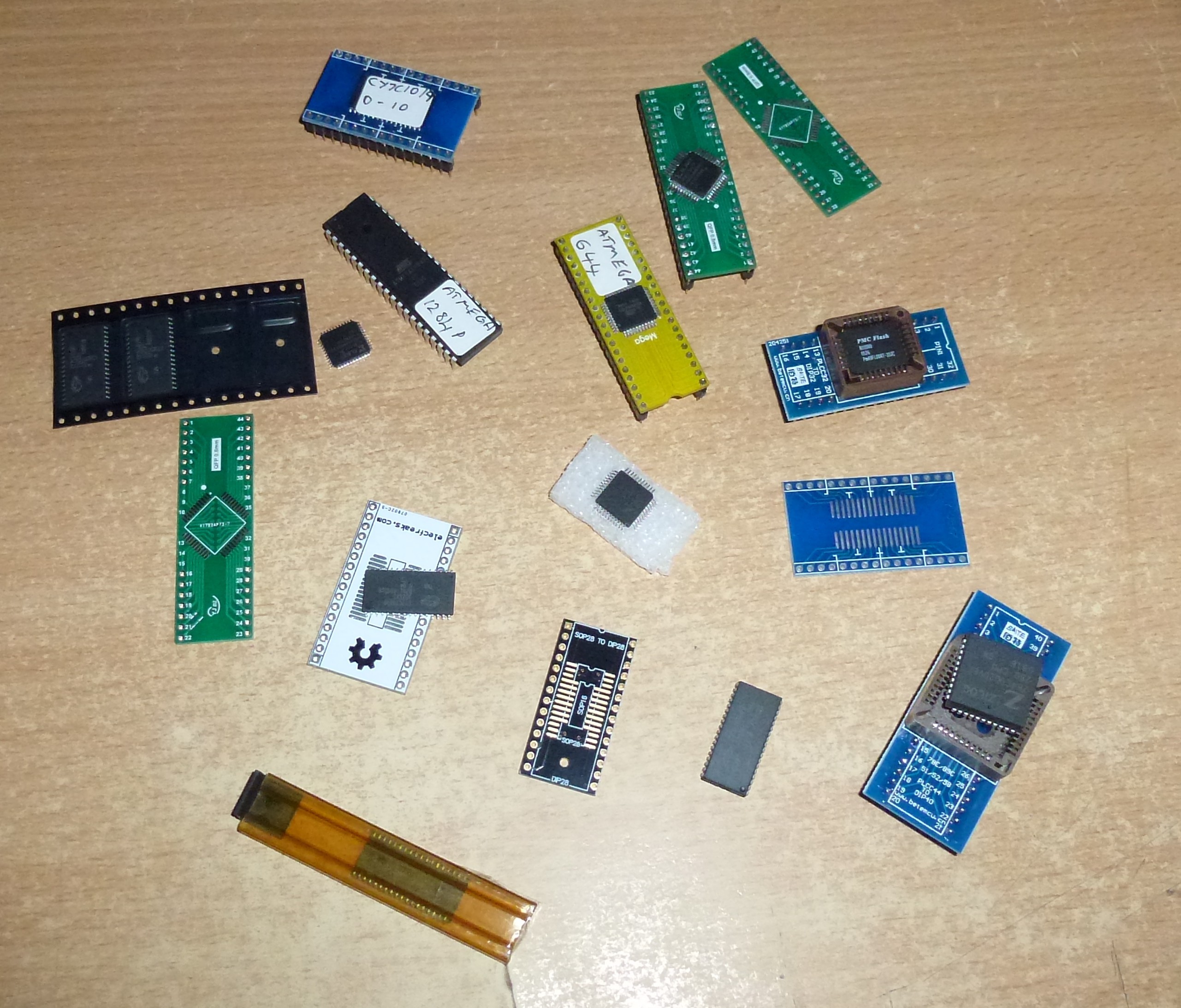
Here are some pics of the development tool I am working with -
This is a development board that I bought on ebay. It is for an atMEGA664. The atMEGA1284 has the same pinout. I had to modify the Arduino IDE to use the 1284. I will use it with the Arduino IDE for low speed proof of concept work using sketch and the USB port. When I am ready to start the VGA side of things I will switch to AVR Studio and program it with the USBasp pictured. The files that came with it had a trojen in some files and changes to the core Arduino java file so started with a new copy of the IDE and made the changes needed. They're not hard to do, just text files, you don't even need to re-compile as the tool-chain already supports the atMEGA1284.

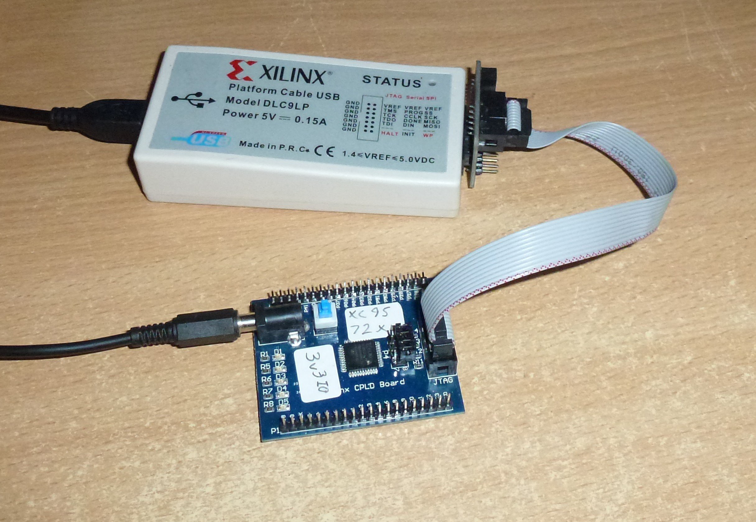
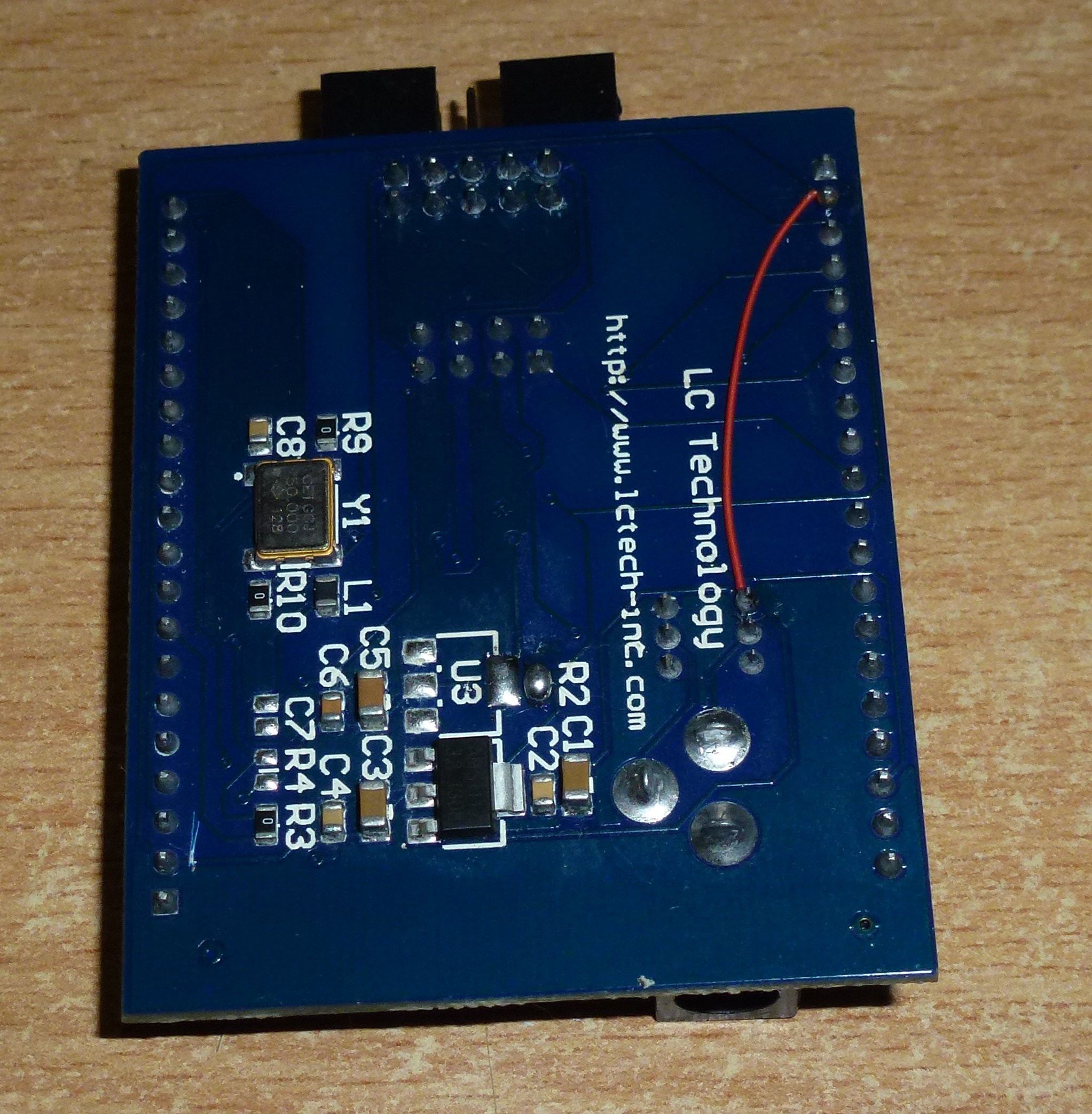
This is a XC9572XL CPLD breakout board. It has a 50MHz active crystal on board. The Xilinx programmer works with the Xilinx ISE for loading the VHDL into the chip.
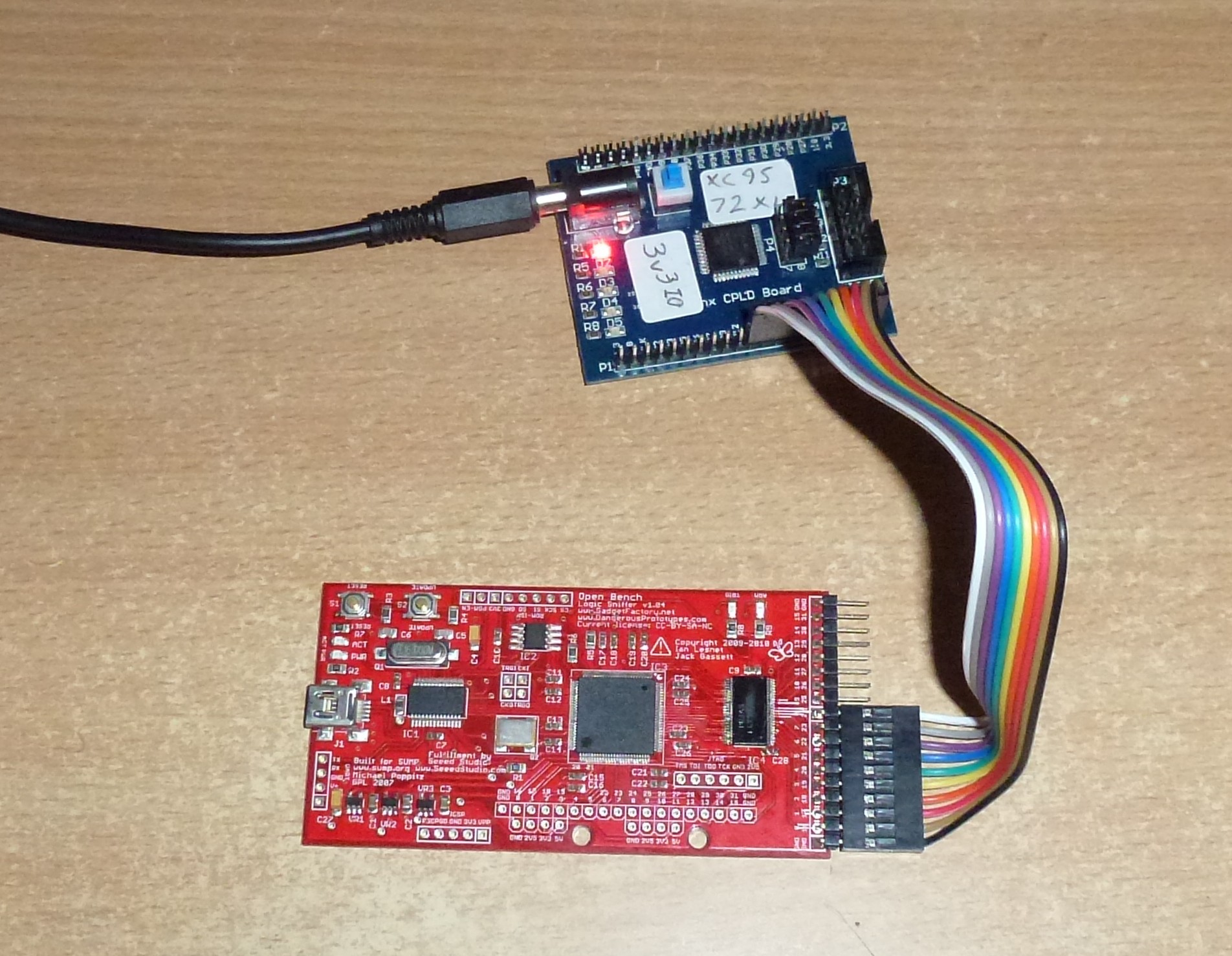
This is an "open bench logic sniffer" that I use to see what's wrong when my VHDL doesn't do what I expect it to do. It scans at 200MHz and is rather cheap. It matches this project well.
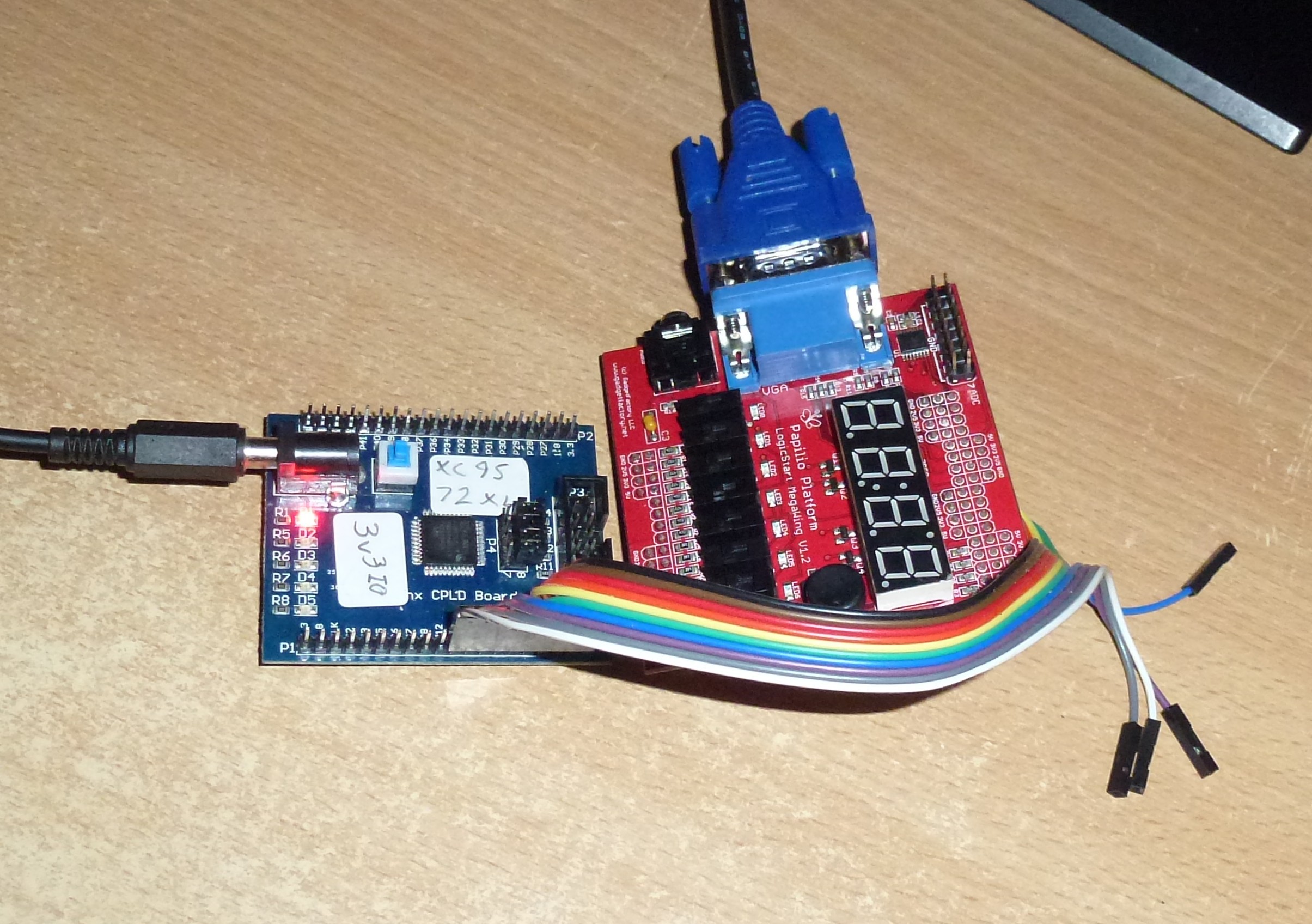
Here the CPLD board is connected to a Papilio One LogicStart MegaWing. I am just using it for the VGA socket.
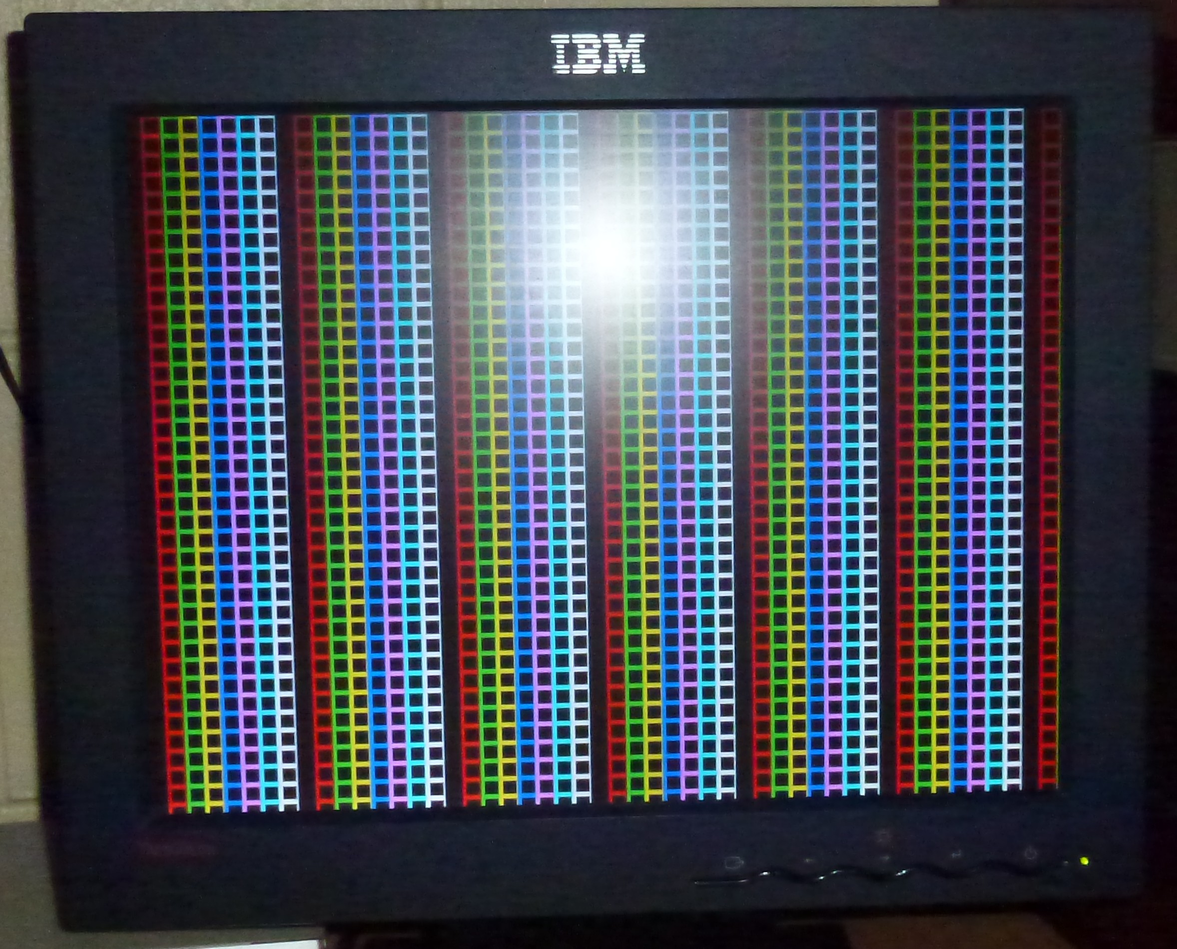
Here is a test pattern being generated by the CPLD as a proof of concept for the VGA timing.
Here is where I am up to. Getting everything to DIP so that I can work on a breadboard.
Just a quick update (02/01/2015) I am waiting for shorting links or jumpers so that I can plug a shield with SRAM on top of the XC9572XL module.
The links arrived.
I moded the CPLD board so that it passes out 5 Volts instead of 1.8 Volts so that I can power the SRAM.
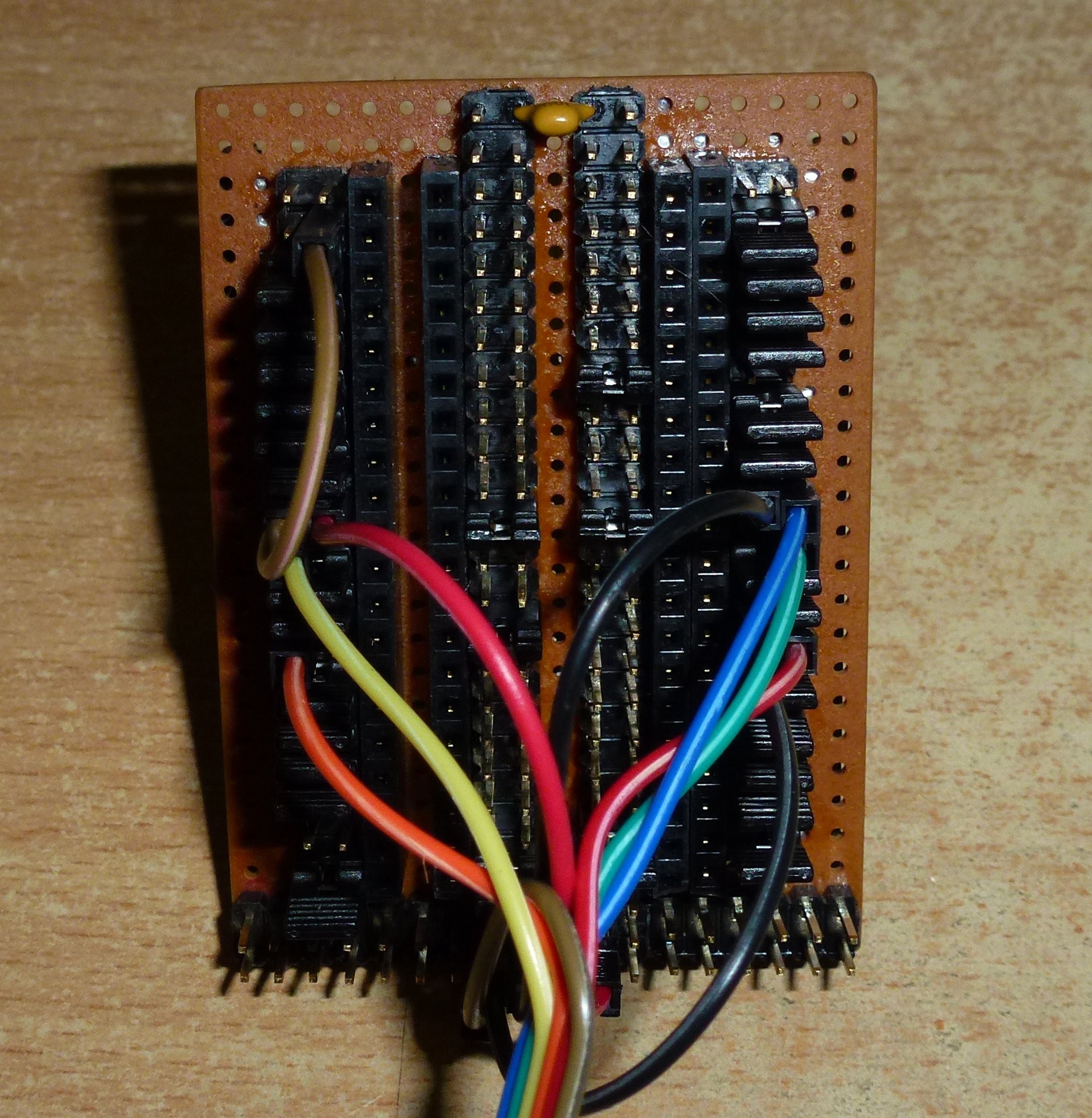
Here is the shield thingy made on strip board. It will accept chips / breakout boards of different widths so I can use it with the atMEGA1284 later on.
And the bottom (messy soldering).
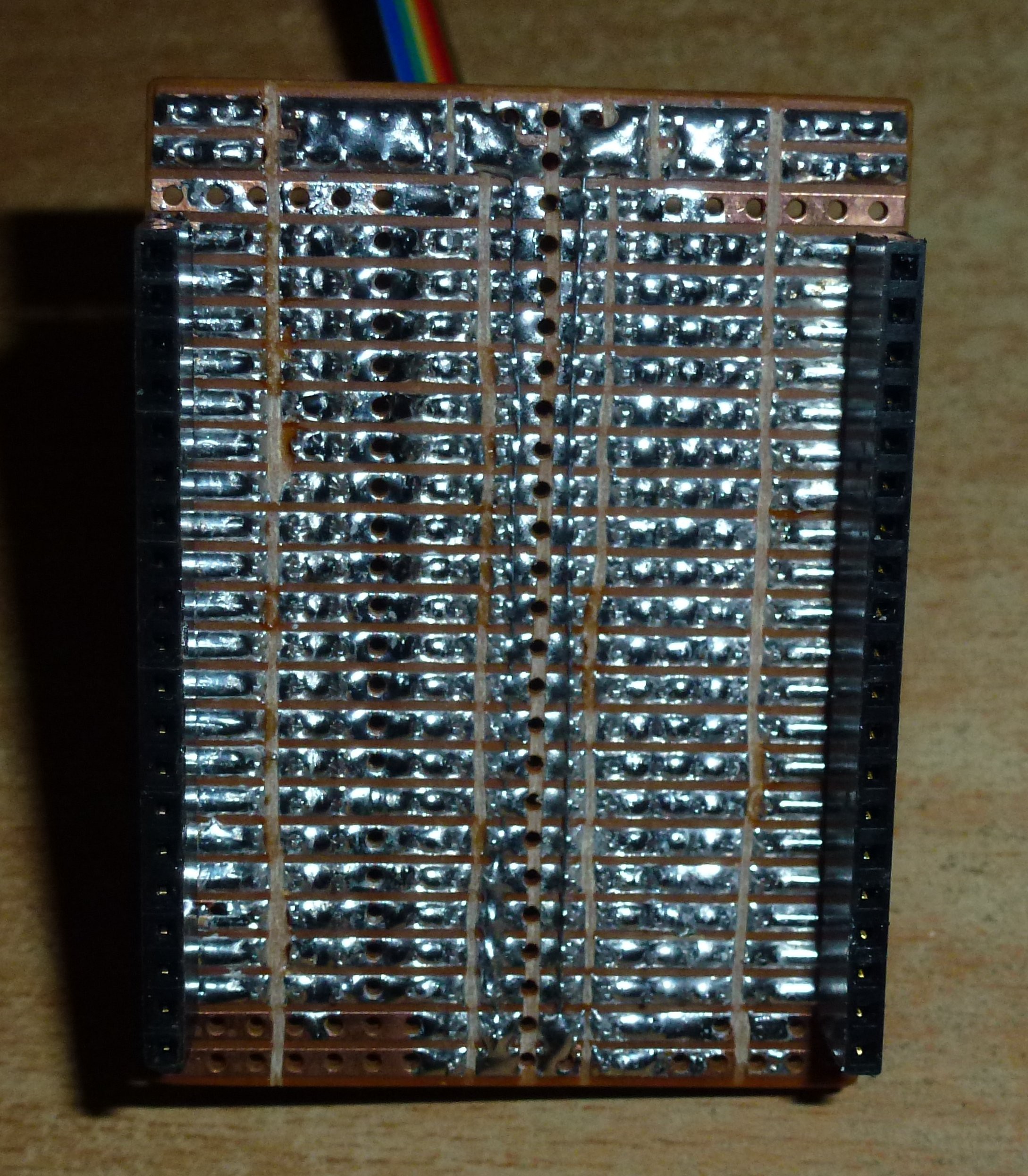
It's messy but I hope it works. I really didn't expect this to run on a bread board with 40 ns access times. Now there is only one wire in a signal path, the rest are the shorting links.
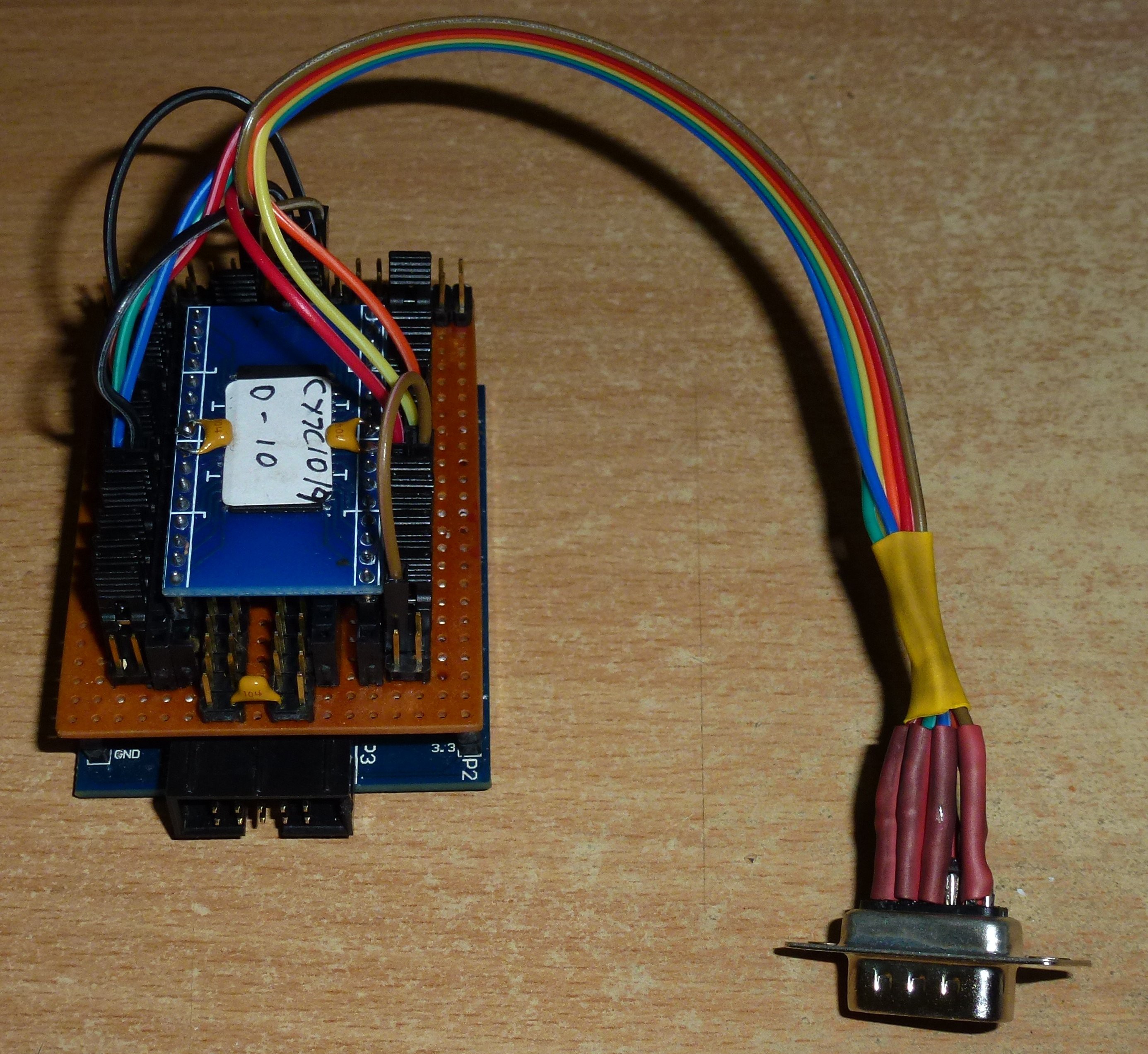
Here are the components apart.
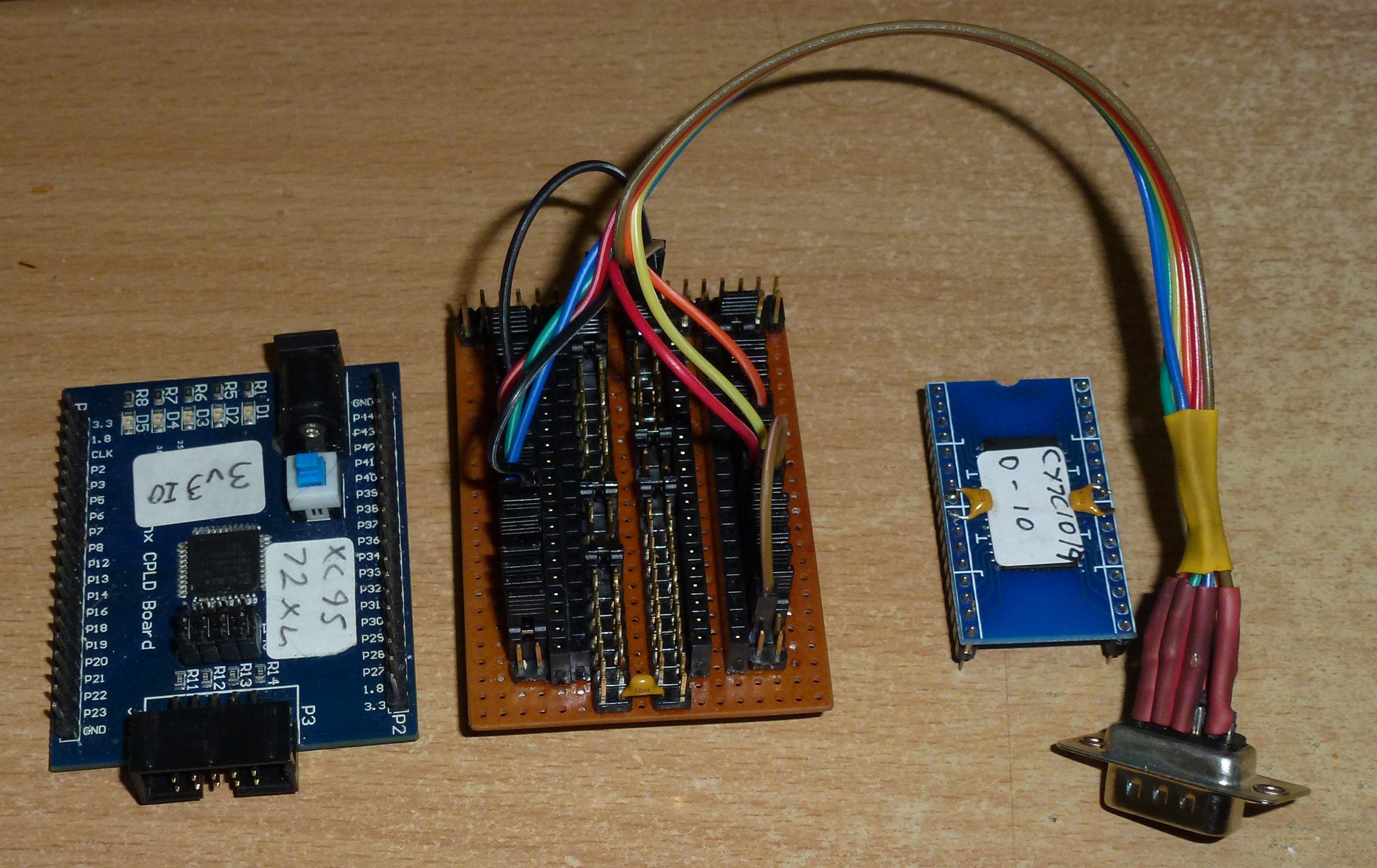
And assembled.
I re-wrote the constraints file to suite the new pinout and tested it with the old VHDL that doesn't use the SRAM and that is working.
Now I have to write some new VHDL and I will post the results when that stage is done.
Here's the old VHLD.
library IEEE;
use IEEE.STD_LOGIC_1164.ALL;
use IEEE.std_logic_unsigned.all;
use IEEE.numeric_std.all;


-- VGA standard 800x600 50MHz
-- VGA actual   400x300 25MHz
-- RAM 120,000  120,000 Bytes at 1 Byte per pixel
-- pixels       400 x 300
-- chr  8 x  8   50 x  37.5
-- chr 16 x 16   25 x  18.75

-- #### HORIZONTAL ####
-- signal  value    units   provisor     domain              time               domain
-- h_active  800   pixels   @ 50 MHz     0000 - 0799    16.000 uS    0.000 - 15.980 uS
-- h_back     64   pixels   @ 50 MHz     0800 - 0863     1.280 uS   16.000 - 17.260 uS
-- h_sync    120   pixels   @ 50 MHz     0864 - 0983     2.400 uS   17.280 - 19.660 uS
-- h_front    56   pixels   @ 50 MHz     0984 - 1039     1.120 uS   19.680 - 20.580 uS

-- Signal                  Freq       Period     Rises after       Duration
-- clk        50,000,000     Hz        20 nS           10 nS          10 nS
-- hc(0)      25,000,000     Hz        40 nS           20 nS          20 nS
-- hc(1)      12,500,000     Hz        80 nS           40 nS          40 nS
-- hc(2)       6,250,000     Hz       160 nS           80 nS          80 nS
-- hc(3)       3,125,000     Hz       320 nS          180 nS         180 nS
-- hc(4)       1,563,500     Hz       640 ns          320 nS         320 nS
-- hc(5)         781,250     Hz     1.280 uS          640 nS         640 nS
-- hc(6)         390,625     Hz     2.560 uS        1.280 uS       1.280 uS
-- hc(7)         195,312.50  Hz     5.120 uS        2.560 uS       2.560 uS
-- hc(8)          97,656.25  Hz    10.240 uS        5.120 uS       5.120 uS
-- hc(9)          48,828.125 Hz    20.480 uS       10.240 uS      10.240 uS
-- hc(10)         24,   ...  Hz    40.960 uS       20.480 uS      20.480 uS


-- #### VERTICAL ####
-- signal     duration       range                    range start            range ends after
-- v_active  600 lines  000 -  599                              0    512        +64   +16  +4+2+1
-- v_back     23 lines  600 -  622   512        +64   +16+8          512        +64+32   +8+4+2
-- v_sync      6 lines  623 -  628   512        +64+32   +8+4+2+1    512        +64+32+16  +4
-- v_front    37 lines  629 -  665   512        +64+32+16  +4  +1    512+128          +16+8     +1

-- signal   rises after
-- h_sync                    any h signal that doesn't repeat in one scanline should be ok
-- vc(0)        1 line
-- vc(1)        2 lines
-- vc(2)        4 lines
-- vc(3)        8 lines
-- vc(4)       16 lines
-- vc(5)       32 lines
-- vc(6)       64 lines
-- vc(7)      128 lines
-- vc(9)      256 lines
-- vc(10)     512 lines


-- ok now some notes
-- the original vga spec is for 1040 clock cycles per h_line
-- which means the h_count will be 11 bit h_count(10 downto 0)
-- there are 666 lines to a frame 9 bit   v_count(9 doen to 0)
-- h_active = 800 clocks = 512 + 256 + 32 - 1

entity XC9572XL is --VGA800x600-50MHz is

    Port (
         CLK      :  in STD_LOGIC;
           H_SYNC   : out STD_LOGIC;
           V_SYNC   : out STD_LOGIC;
           RED      : out STD_LOGIC;
           GRN      : out STD_LOGIC;
           BLU      : out STD_LOGIC;
--          C_ACTIVE : out STD_LOGIC;
--          C_SYNC   : out STD_LOGIC;
         LED1     : out STD_LOGIC;
         LED2     : out STD_LOGIC;
         LED3     : out STD_LOGIC;
         LED4     : out STD_LOGIC
         );

end XC9572XL;--VGA800x600-50MHz;

architecture Behavioral of XC9572XL is--VGA800x600-50MHz is

--signal nclk       : STD_LOGIC;

signal h_counter  : STD_LOGIC_VECTOR (10 downto 0) := "11111111111";
signal h_active   : STD_LOGIC;
signal v_counter  : STD_LOGIC_VECTOR (10 downto 0) := "11111111111";
signal v_active   : STD_LOGIC;

signal f_counter  : STD_LOGIC_VECTOR (4 downto 0) := "00000";
signal dot_x      : STD_LOGIC_VECTOR (5 downto 0) := "000001";
signal dot_x_dir  : STD_lOGIC := '1';
signal dot_y      : STD_LOGIC_VECTOR (5 downto 0) := "000000";
signal dot_y_dir  : STD_LOGIC := '1';
signal dot_flag   : STD_LOGIC;
signal edge_flag  : STD_LOGIC;

signal h_highlight : STD_LOGIC;
signal v_highlight : STD_LOGIC;

signal chrr        : STD_LOGIC_VECTOR (7 downto 0);
signal px          : STD_LOGIC;

--signal h_sync_reg : STD_LOGIC;
--signal h_actv_reg : STD_LOGIC;
--signal v_sync_reg : STD_LOGIC;
--signal v_actv_reg : STD_LOGIC;

begin

-- update horizontal counter and flags
process (CLK)--, h_counter, v_counter)
begin
if rising_edge(CLK) then
    h_counter <= h_counter + 1; -- start of horizontal code
    if (h_counter = 0) then -- start of horizontal active period
        h_active <= '1';
    end if;


    if (h_counter > 390 and h_counter < 408) then -- debugging block
        h_highlight <= '1';
--    end if;
--    if (h_counter = 407) then
   else
        h_highlight <= '0';
    end if;


    if (h_counter = 800) then -- end of horizontal active period
        h_active <= '0';
    end if;
    if (h_counter = 856) then -- start of horizontal sync
        H_SYNC <= '0';
    end if;
    if (h_counter = 976) then -- end of horizontal sync
        H_SYNC <= '1';

        v_counter <= v_counter + 1; -- start of vertical code
        if (v_counter = 0) then -- start of vertical active period
            v_active <= '1';
        end if;


        if (v_counter = 291) then -- debugging block
            v_highlight <= '1';
        end if;
        if (v_counter = 307) then
            v_highlight <= '0';
        end if;


        if (v_counter = 600) then -- end of vertical active period
            v_active <= '0';
        end if;
        if (v_counter = 637) then  -- start of vertical sync
            V_SYNC <= '1';
        end if;
        if (v_counter = 643) then -- end of vertical sync
            V_SYNC <= '0';
        end if;
        if(v_counter = 666) then -- end of vertical frame
            v_counter <= "11111111111";
            f_counter <= f_counter + 1;
            if (f_counter = "11111") then
                if (dot_x = 0) then
                    dot_x_dir <= '1';
                end if;
                if (dot_x = 48) then
                    dot_x_dir <= '0';
                end if;
                if(dot_y = 0) then
                    dot_y_dir <= '1';
                end if;
                if (dot_y = 35) then
                    dot_y_dir <= '0';
                end if;
                if(dot_x_dir = '1') then
                    dot_x <= dot_x + 1;
                else
                    dot_x <= dot_x - 1;
                end if;
                if(dot_y_dir = '1') then
                    dot_y <= dot_y + 1;
                else
                    dot_y <= dot_y -1;
                end if;
            end if;
        end if;
    end if; -- end of vertical code

    if(h_active = '1' AND v_active = '1' AND (h_counter = 1 OR h_counter = 800 OR v_counter = 1 OR v_counter = 600)) then
      edge_flag <= '1';
    else edge_flag <= '0';
    end if;

    if (h_counter = 1040) then -- end of horizontal line
        h_counter <= "11111111111";
    end if; -- end of horizontal code

    if ((h_counter(9 downto 4) = dot_x(5 downto 0)) AND (v_counter(9 downto 4) = dot_y(5 downto 0))) then
        dot_flag <= '1';
    else
        dot_flag <= '0';
    end if;
    --dot_flag <= '1';

end if;

end process;

--process (nclk)
--begin
--if rising_edge(CLK) then
--    h_counter <= h_counter + 1; -- start of horizontal code
--end if;
--end process;

--nclk <= not CLK;

--with v_counter (3 downto 1) select chrr <=
--  "00000000" when "000",
--  "00111110" when "001",
--  "01100110" when "010",
--  "01100110" when "011",
--  "00111110" when "100",
--  "01100110" when "101",
--  "01100110" when "110",
--  "00111110" when "111",
--  "00000000" when others;

with v_counter (3 downto 1) select chrr <=
  "11111111" when "000",
  "10000001" when "001",
  "10000001" when "010",
  "10000001" when "011",
  "10000001" when "100",
  "10000001" when "101",
  "10000001" when "110",
  "11111111" when "111",

  "00000000" when others;

with h_counter (3 downto 1) select px <=
  chrr(0) when "000",
  chrr(1) when "001",
  chrr(2) when "010",
  chrr(3) when "011",
  chrr(4) when "100",
  chrr(5) when "101",
  chrr(6) when "110",
  chrr(7) when "111",
  '0'     when others;

--LED1 <= '1';
--LED2 <= not '1';
--LED3 <= '0';
--LED4 <= not '0';

RED <= ((px XOR dot_flag) AND h_active AND v_active AND (h_counter(4) XOR (v_highlight AND h_highlight) XOR v_counter(4)));
GRN <= ((px XOR dot_flag) AND h_active AND v_active AND (h_counter(5) XOR (v_highlight AND h_highlight) XOR v_counter(4)));
BLU <= ((px XOR dot_flag) AND h_active AND v_active AND (h_counter(6) XOR (v_highlight AND h_highlight) XOR v_counter(4)));


--H_ACTIVE <= h_actv_reg;
--H_SYNC   <= h_sync_reg;
--V_ACTIVE <= v_actv_reg;
--V_SYNC   <= v_sync_reg;
--C_ACTIVE <= h_actv_reg AND v_actv_reg;
--C_SYNC   <= h_sync_reg XOR v_sync_reg;


end Behavioral;
Damn! No markup for VHDL!
Anyway, I am doing this as an exercise in learning VHDL. The Xilinx XC9572XL simply doesn't have enough pins, there are only about three or four left after the SRAM and VGA are accounted for.
This chip has enough logic to do one line at a time under the control of an ATmega. The larger XC95144XL could probably do the full frame without any assistance.
I will order a XC95144XL in a QFP100 package. I really didn't want to use any 'hard to solder' chips.
Perhaps I should think about using a wide bus 'level translator' for the Z80 and then just use all 3.3 Volt chips for everything else. Then I can use a much larger FPGA and do lots of nice things with the video.
I'm a bit lost at the moment with which way to go. It's difficult to mix an old 5 Volts CPU with modern chips.