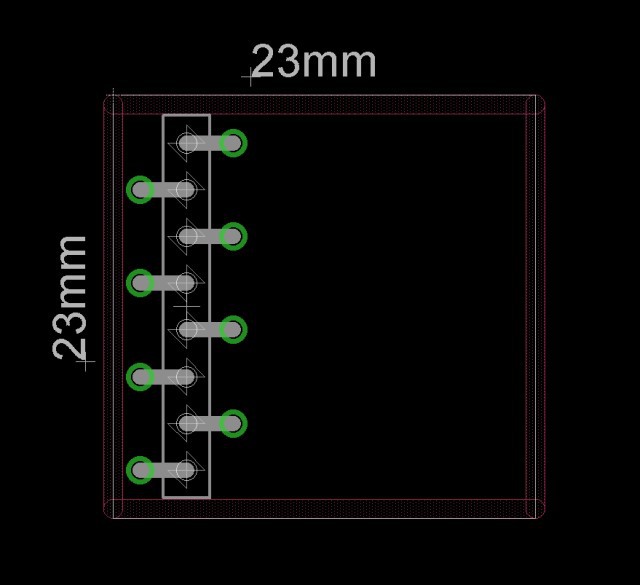
Proposal for the module board:
Modules are arranged in a 2x2x5 matrix = 20 modules in a single PocketQub
Eight long pinheads go up through the five modules of each quadrant.
Here is a picture of the proposed pinheader,
Five pins are unique UARTs (halfduplex) for each of the five modules in one column, additionally a +3V3 and a GND pin.
I planned a unique power latching for each module, but this would require additional five pins. Instead, there might be a latching for each column, and to prevent other modules of this column to be shorted by another module, I´d suggest to use a polyfuse on each module mandatory.
Let me know if you got a better idea to arrange/connect the modules which saves more space.
NOTE: I don´t want a bus system, because I want to avoid unnessecery coordination between the modules´ owners and avoid a bus failure if one module shorts the bus.

 Paul Kocyla
Discussions
Become a Hackaday.io Member
Create an account to leave a comment. Already have an account? Log In.
[this comment has been deleted]
This is a connector from würth electronics with a through hole to pass the pinheaders through multiple boards. This was just a proposal. Maybe there are better connectors around which save space on the boards.
You are welcome to participate in this project - the design has not been defined by this time, so everything is open yet.
The idea is to find 20 participants who design one board each and make a complete system in the end.
The launch/test costs can be divided by the number of participants so we can afford a launch of an 1U pocketqub
Are you sure? yes | no
Hello,
Sorry if the following suggestions or comments are too late and seem not relevant-
How about a CAN bus (common in automotive) as it is very highly reliable and differential, and many modules can be on same 2 wires. Coordination is automatically managed by CAN block withing MCU. You just need to assign different base address to each module in software and ask them to limit their CANid to a range
1.b if the host requirement is to have UART, maybe one node can be CAN to UART translator.
1.c To reduce shorting potential, mandate a common CAN transceiver IC from are reliable company like Infineon, Automotive grade (instead of commercial, iits just few cents more).
Are you sure? yes | no
1.c. Even this isn't a hard requirement; use open-drain or open-collector logic. That way, driving the signal consists either of pegging it to ground, or letting it float (a pull-up resistor is used to restore the 'high' voltage level). On a MCU without built-in CAN-bus technology, you can bit-bang this by setting the output for an I/O to low, and just switch the I/O pin between input (float signal high) and output (drive low). As a side benefit, when you float a signal high, you can also use the same I/O pin as a real input for true bidirectional behavior. No need to use two I/O pins as you might find on some designs.
Are you sure? yes | no
Yes, that seems to be the best way to do it. We already changed the development into this direction. There will be only four wires: +,GND and CAN
Are you sure? yes | no