Trinket Probe
Inspired by the Superprobe and tiq projects, and a comment on the contest announcement suggesting a Superprobe-esque project
Inspired by the Superprobe and tiq projects, and a comment on the contest announcement suggesting a Superprobe-esque project
To make the experience fit your profile, pick a username and tell us what interests you.
We found and based on your interests.
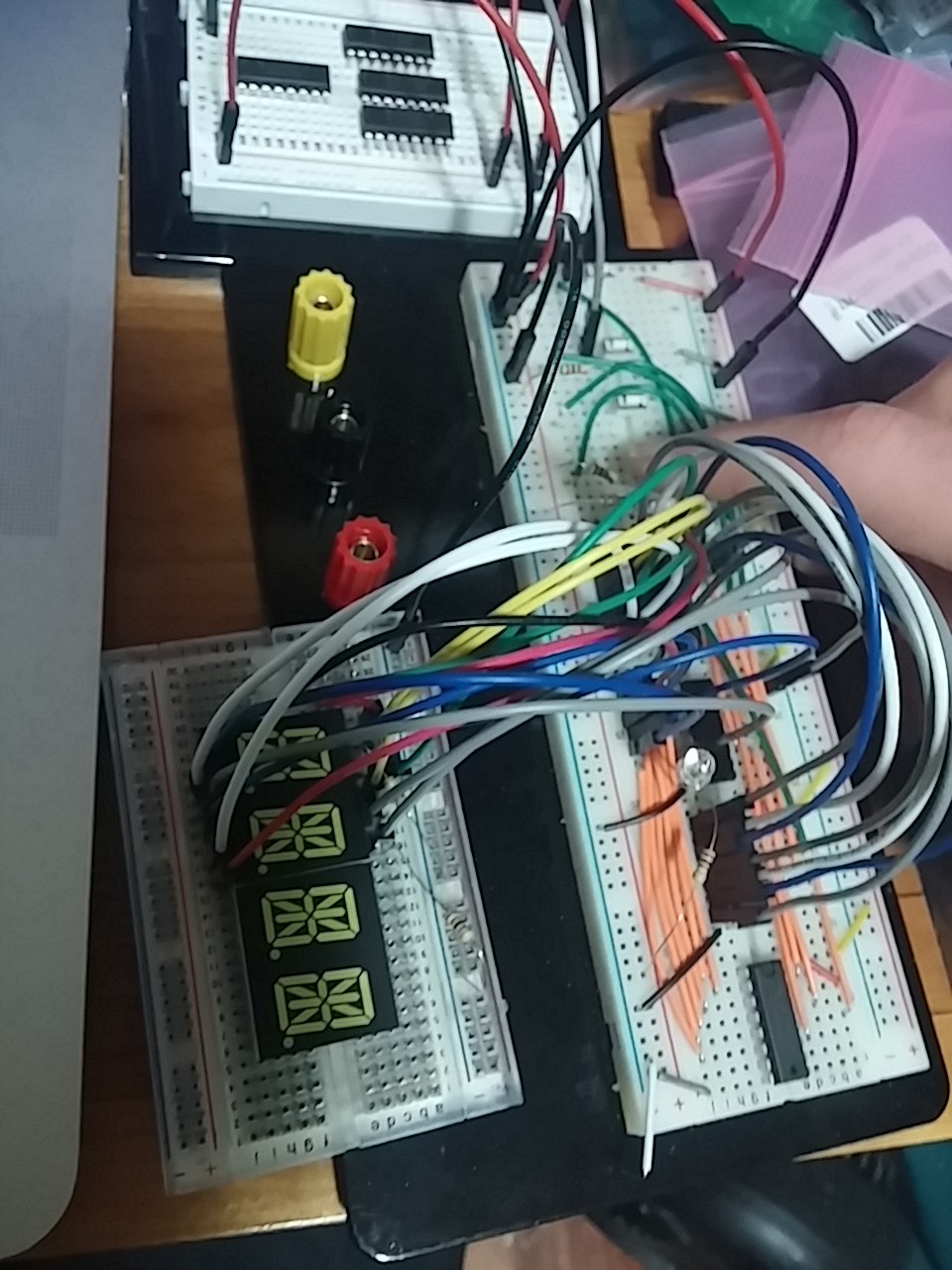
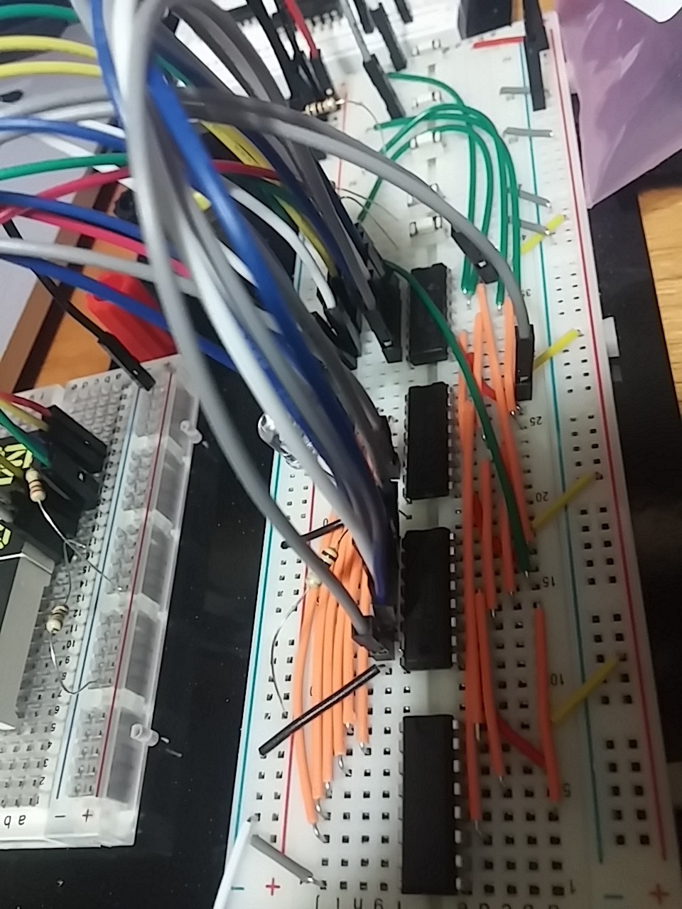
I've got four 74HC595s on a breadboard, and I'm trying to get them to drive the 14-segment display. All I've gotten so far, though, is garbage data going through them. At first, I couldn't get them to accept data at all. Then, for some reason, they started accepting data, but nothing was displayed. I eventually figured out that this was because the display is common cathode, and I'd hooked it up as common anode—I thought I'd tried it earlier as common cathode and discovered it was really common anode, but I guess I didn't. Anyway, it sometimes lights up random-seeming segments now, if I'm lucky. The procedure I'm following is to either clock in bits using the buttons on the breadboard or use shiftOut() on my Arduino, then press the latch button, then press each /OE button individually to see what each pair of shift registers contains. Unfortunately, right now, they're only lighting up the discrete LED I hooked up to make 16 LEDs connected to each pair of shift registers.
Someone on the Arduino forums mentioned shiftOut() being too fast for 595s (though the datasheet says they should be fine well above the Arduino's clock frequency), and the failure when I was clocking in data manually could have been because the buttons aren't debounced at all. Not sure. I will have to take it to my hackerspace and use the logic analyzer.


| GND | 3.3 V |
| 5 V | ADC in |
| Vpu (0–5 V for pullup resistors) | Aux (freq. in/PWM out) |
| CLK | MOSI |
| CS | MISO |
Modes: everything the Superprobe does, with configurability the original didn't have, plus:
Also, probe modules can have their own drivers stored in EEPROM chips. Maybe use Bitlash?
Look into: how three-state shift registers work, charlieplexing
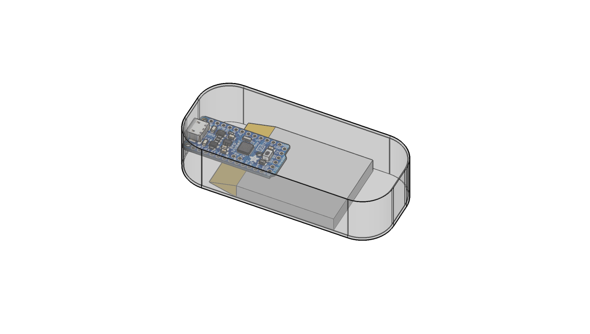
I'm going to try to fit this in an Adafruit Altoids Gum tin, so it needs to be compact. I'm making a 3D CAD model in SketchUp to make sure it all fits:

That battery is the SparkFun 1000 mAh one; it's the only one from either store that fits in the case according to my model. Left to add: the display (4-digit 14-segment white LED), the battery backpack, the buttons, the probe connector, etc. Except the display, they're all pretty small, so I don't think they'll be hard to fit in.
Create an account to leave a comment. Already have an account? Log In.
Become a member to follow this project and never miss any updates