As it turns out the monitor wont go back to its last state when it resumes getting power, I kind of figured on that.
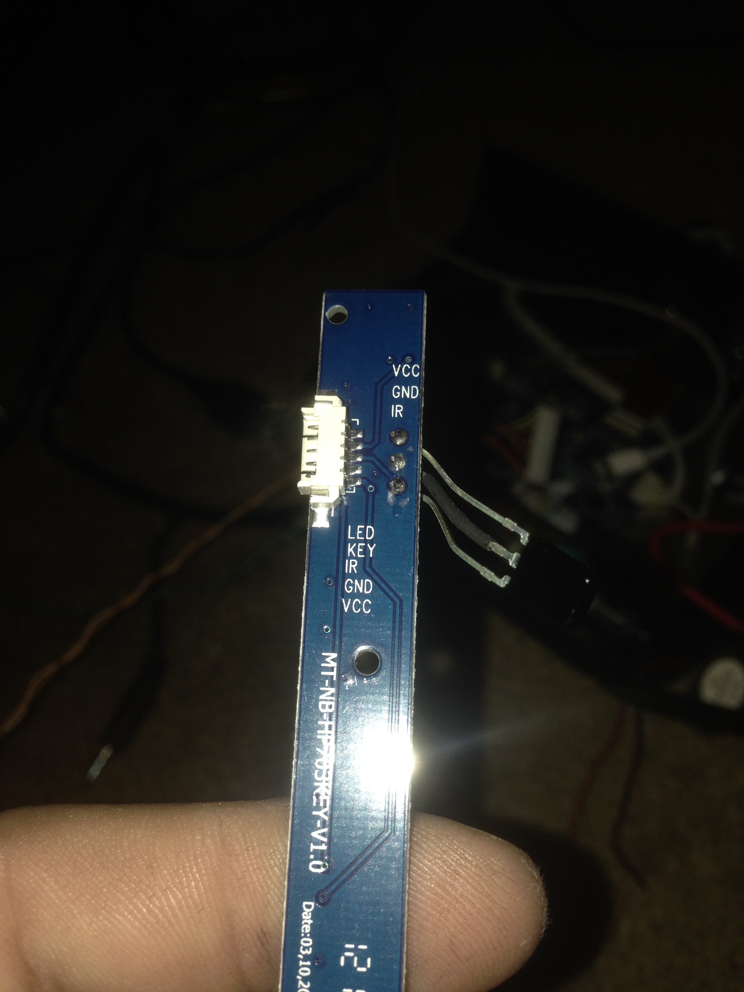
Pulling the button PCB I found this to my surprise!
LED goes to an unpopulated LED, 3.3v when on, 0v when off... NOTED, that will be going to an IO on the Pi, no need to feed that to the button PCB
Key is the output of the buttons, there is a pulldown on that pin, and each button (besides power) has a resistor to then act as a voltage divider, power is 3.3v, source is 3v, etc NOTED... Ill also be taking that to an IO, but also leaving the original signal path intact
IR is the IR output, once again, that will also be going to an IO, no need to send that to the controller
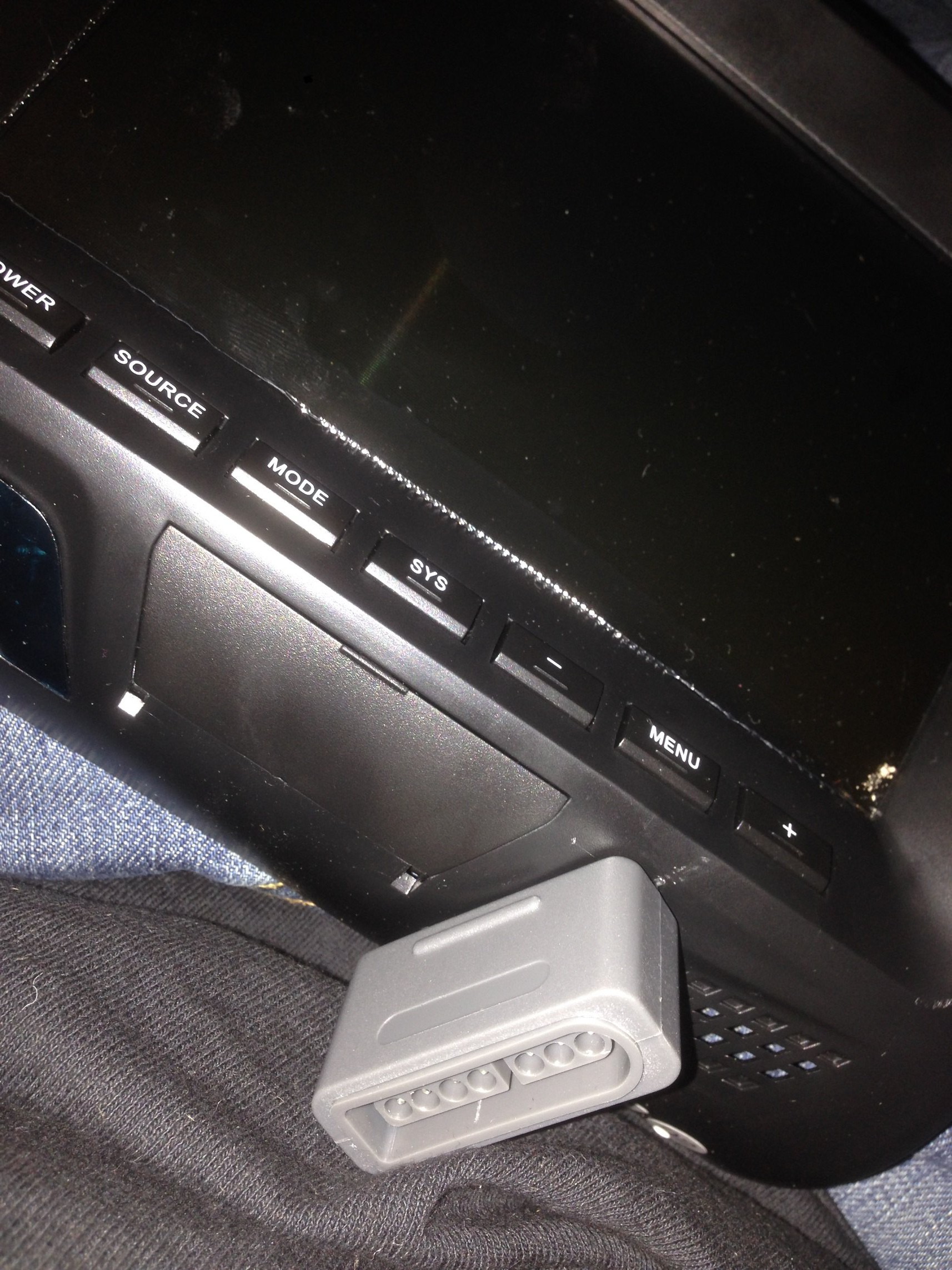
Next is the SNES Controller, that was as easy as a quick drill, and some hotglue to get the extension cable in place
The last step is to get all these thing connected, and I dont want to hardwire them all the the RPI, I want an easy way to disconnect the monitor from the headrest. I picked DB9 as my preferred connector, I need 8 signals, and
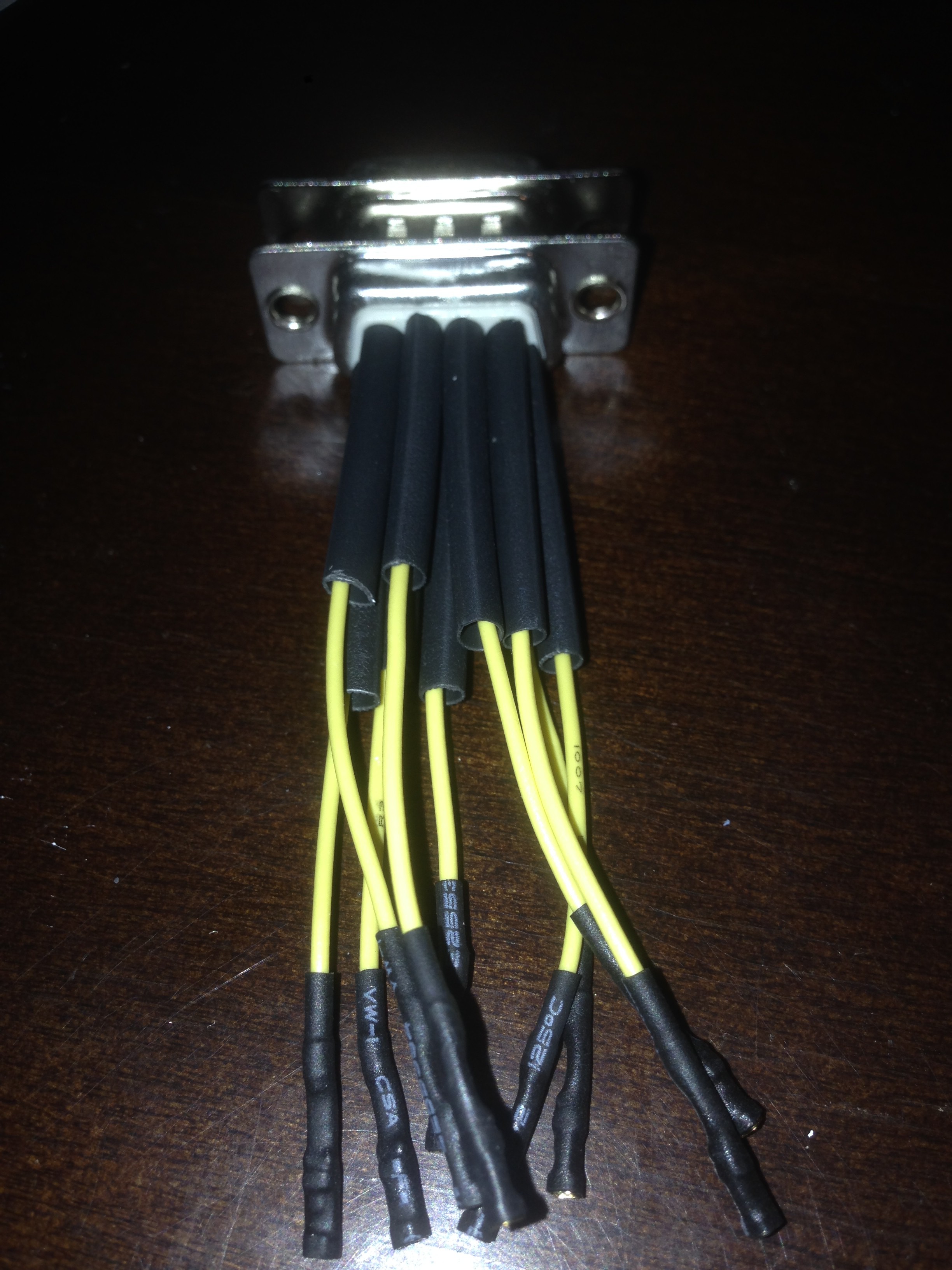
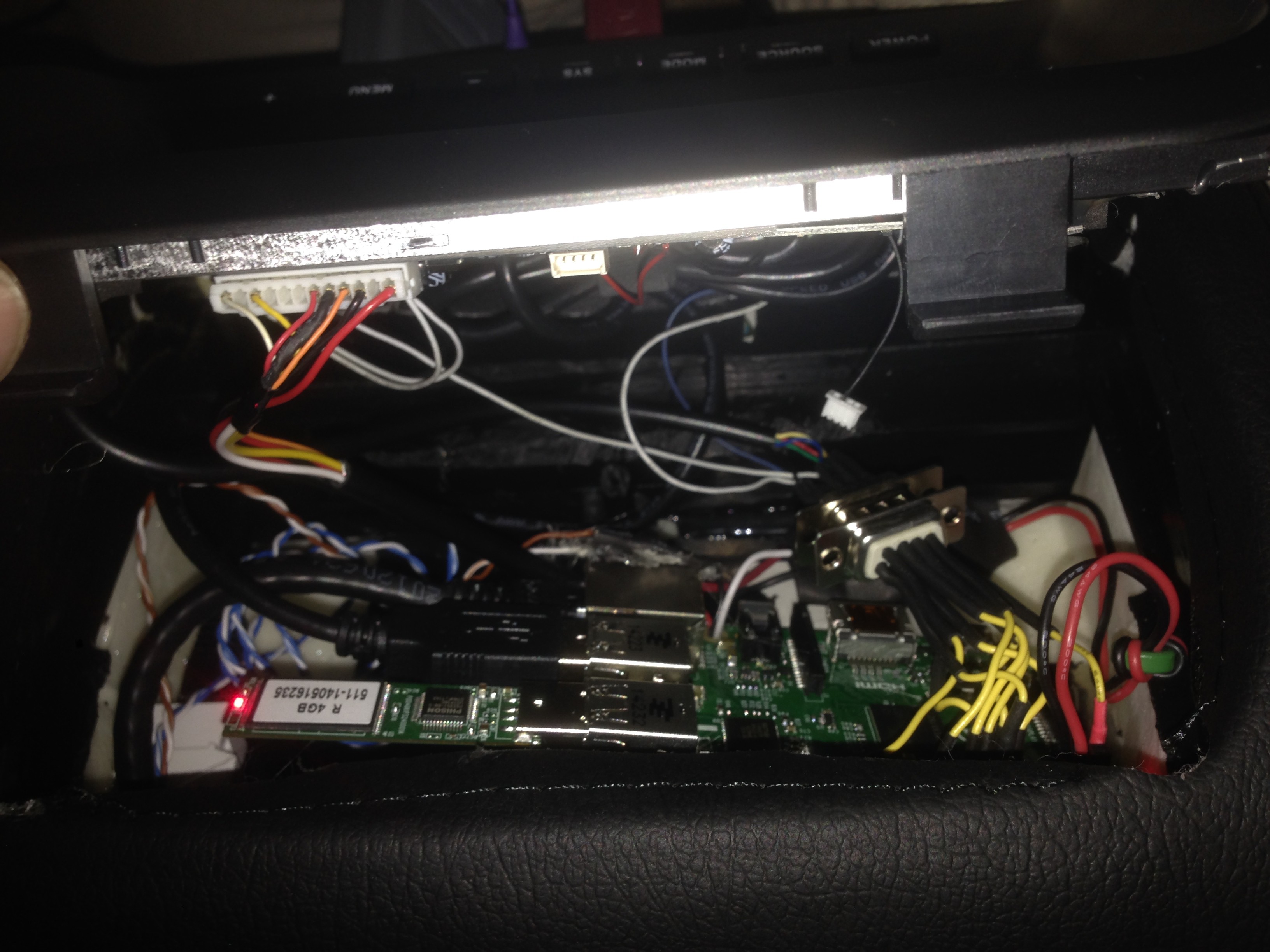
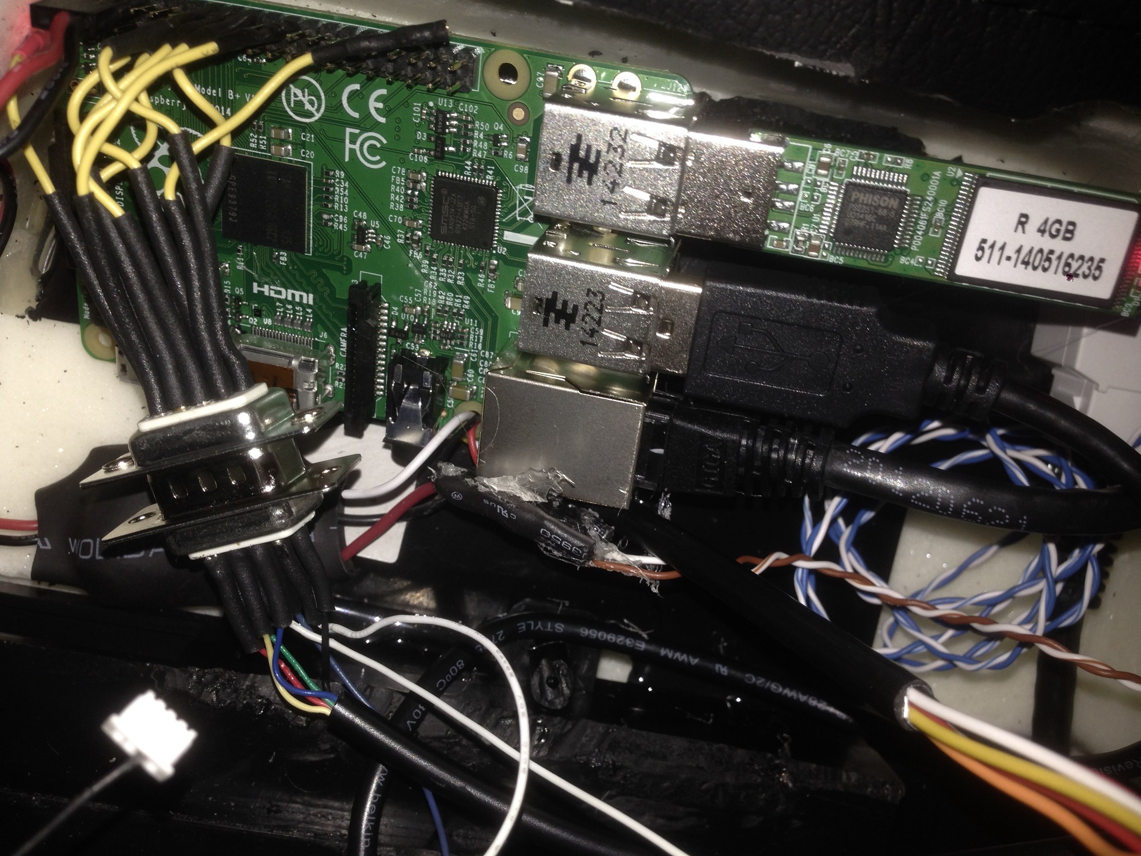
the jumpers from the DB9 to RPI soldered, not heatshrunk yet
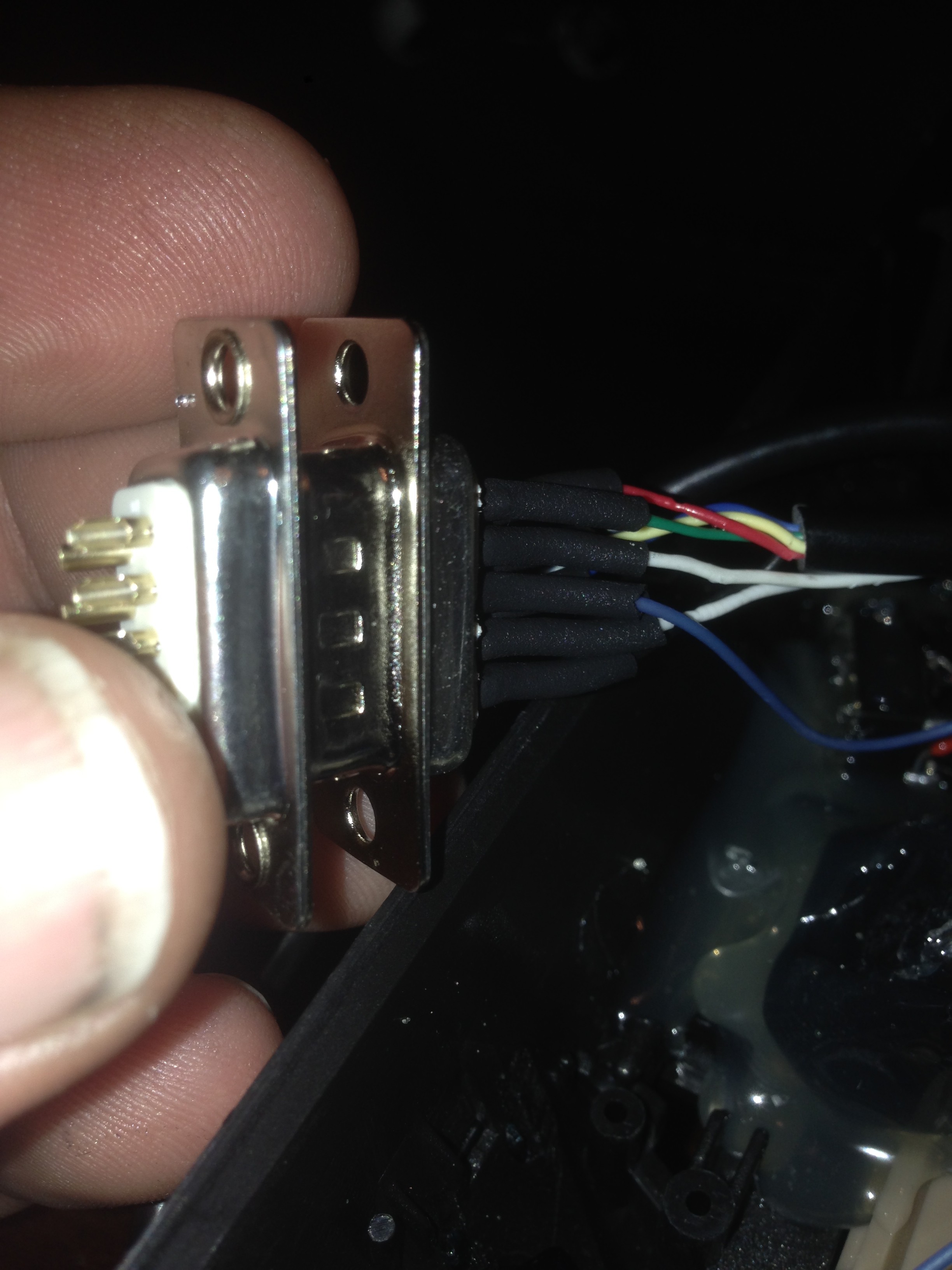
This is the monitor side DB9
I used the following pinout
DB9Pin -- Label -- RPI Pin -- SNESCable Color
1 -- 3.3v -- 1 -- green
2 -- Screen LED -- 13 --
3 -- Screen KEY -- 15 --
4 -- Screen IR -- 11 --
5 -- Ground -- 14 -- black
6 -- SNES Data -- 22 -- red
7 -- SNES Latch -- 16 -- yellow
8 -- SNES Clock -- 18 -- blue
9 -- SPARE -- 0 --
Here you can see the DB9 connected and ready to go
The last thing that I didnt mention is I am using a cat6 keystone jack to provide the connection from the rest of the car
Pins 1,2,3,6 go right to the Ethernet port on the pi, and pins 4,5 provide power the screen and the UBEC
pins 7,8 are for a future feature to allow the headrest monitor to gracefully shutdown and cut power to its own relay
Next stop, SOFTWARE!
Discussions
Become a Hackaday.io Member
Create an account to leave a comment. Already have an account? Log In.