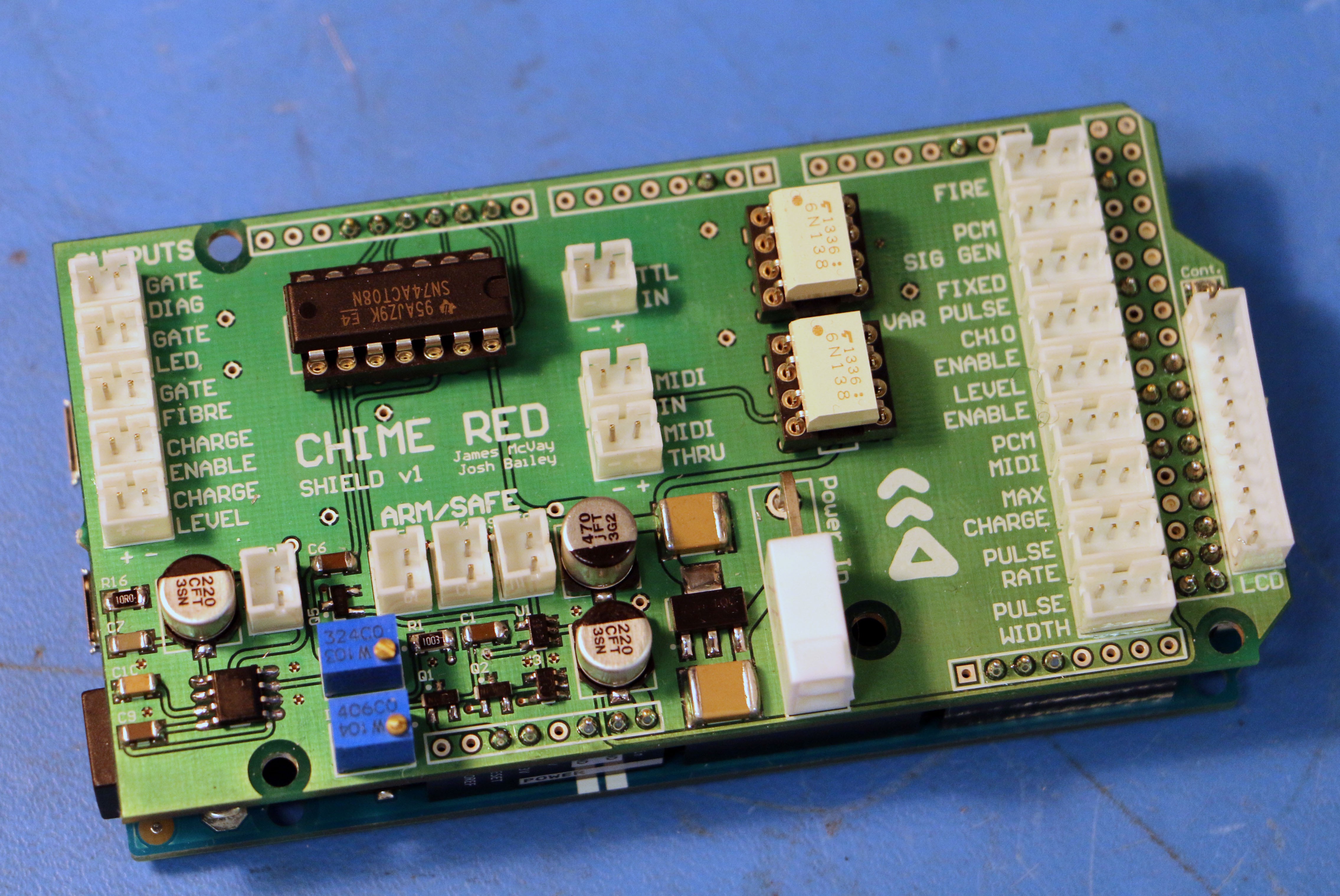
The Populated Arduino Due Shield, mounted on a Due.
- AND gate to prevent outputs from being triggered when the interlock isn't engaged as well as driving the TTL outputs
- Interlocked based on Keyswitch Input and RC + Schmitt Trigger Oneshot (Due outputs flail on Startup)
- Amplifier for Speaker Output to Simulate Gate Output at Bottom LHS
- Potentiometers control Speaker Volume and Interlock Startup Delay Period
- 6N138's for MIDI Input and Optoisolated TTL Input
- 2 Pin Connectors for Gate Fibre, Status LEDs and TTL Outputs on the LHS
- 3 Pin Connectors for Push Button Inputs as Labelled on RHS
- Status LCD connector on RHS with Contrast Pot above

Discussions
Become a Hackaday.io Member
Create an account to leave a comment. Already have an account? Log In.