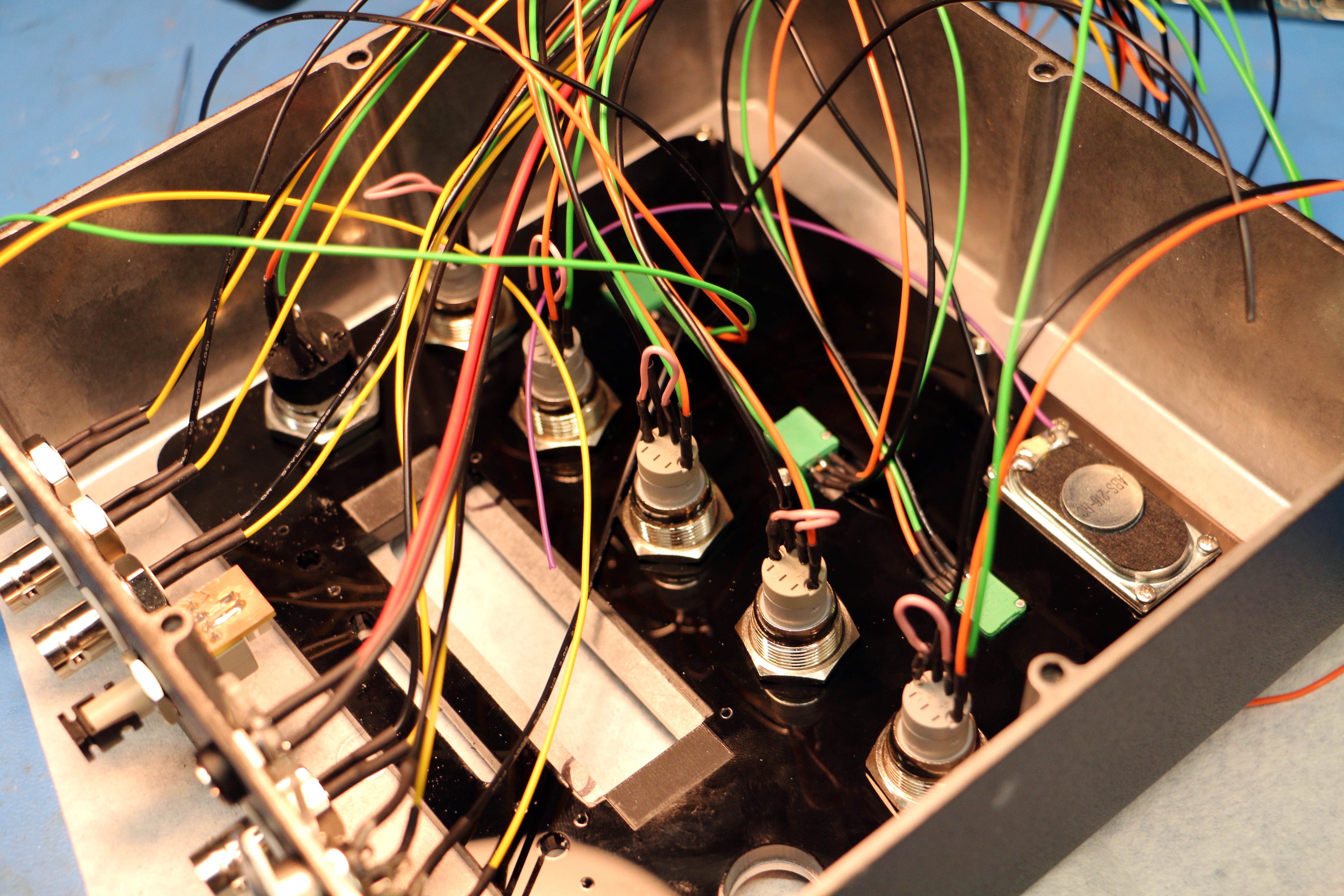
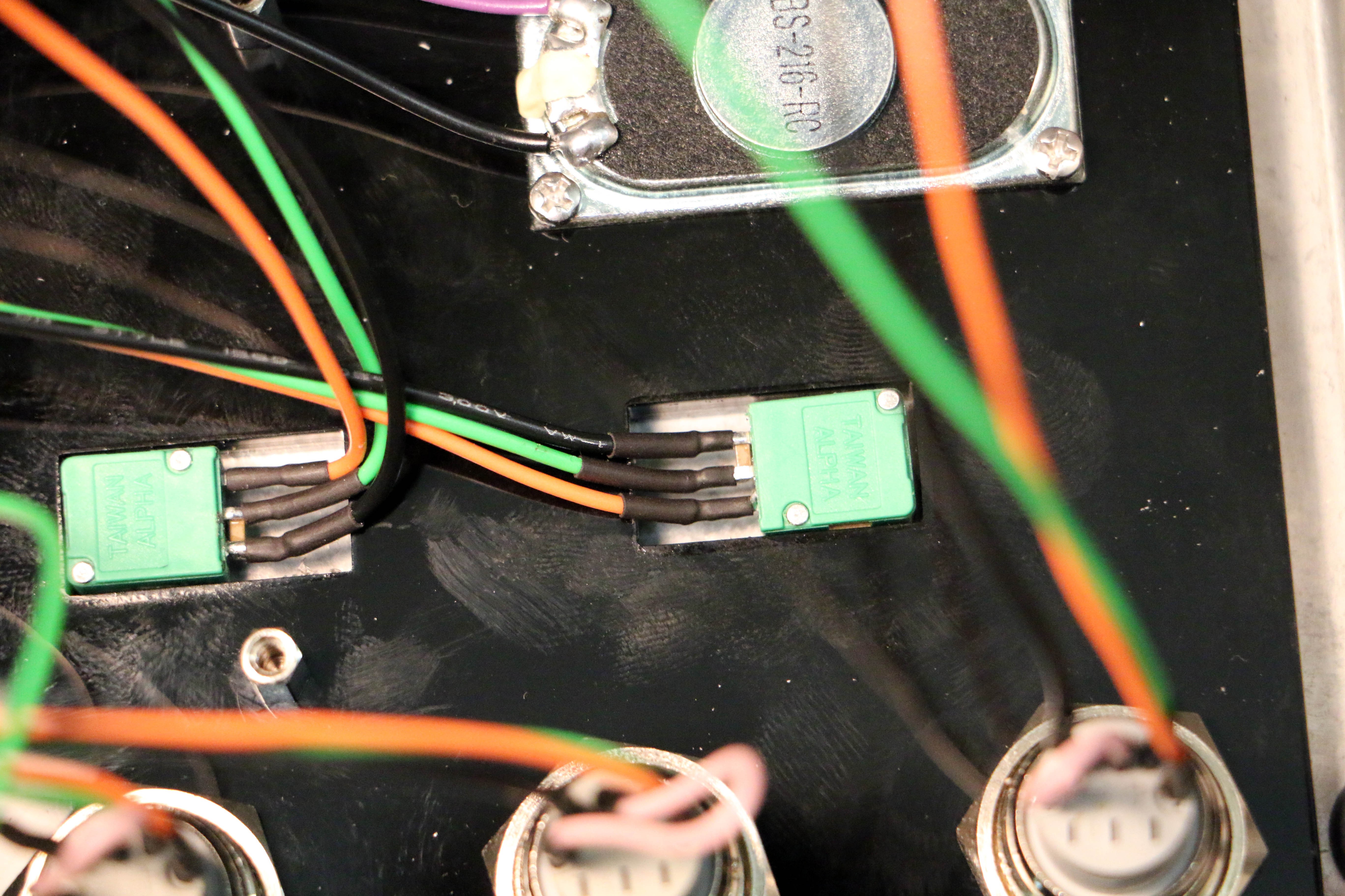
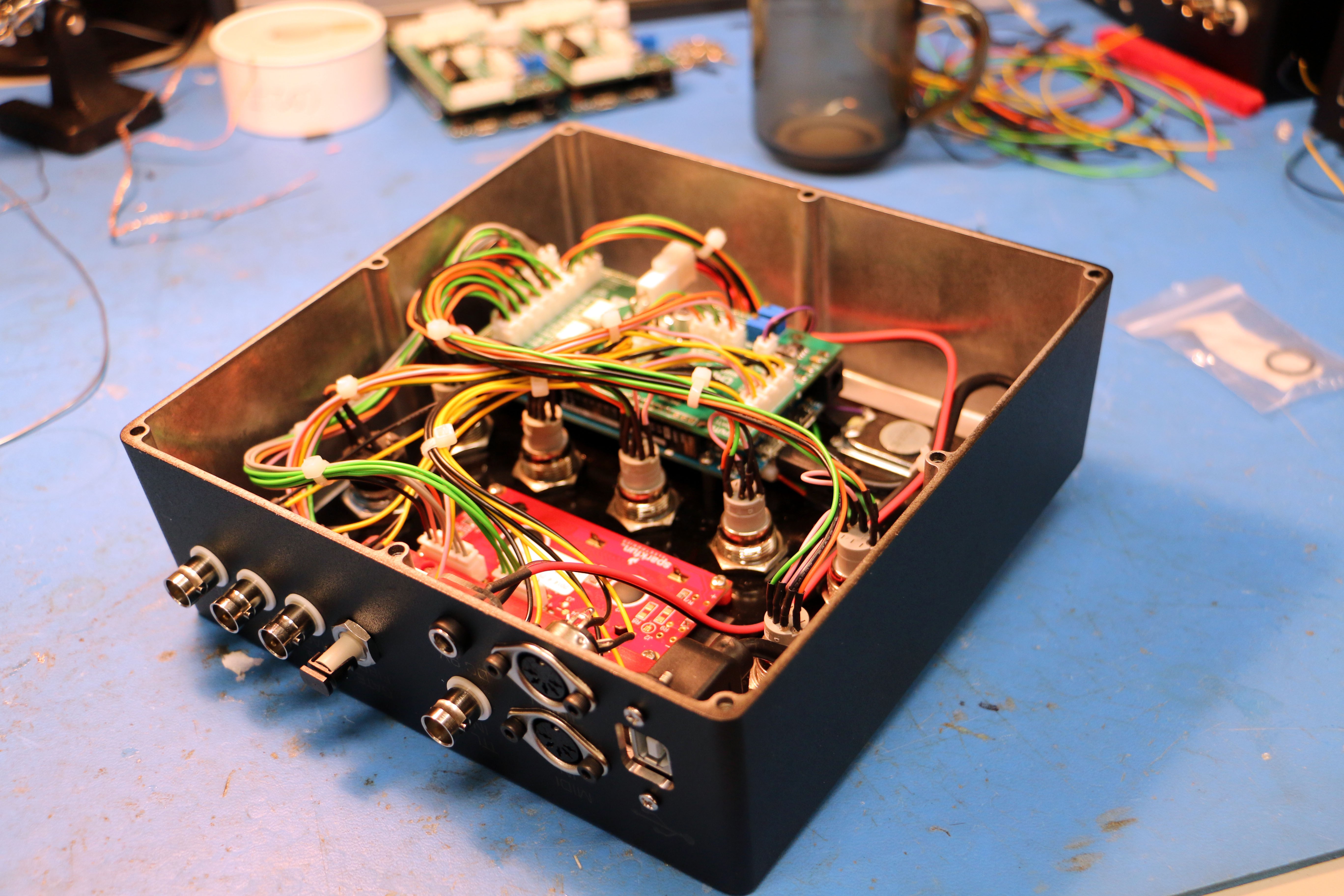
Having soldered in excess of 400 wires to buttons and various connectors, an acrylic shim is created to mount the Arduino Due, Speaker, LCD display and LCDs to. The pushbuttons and keyswitch mounting are used to bolt the shim to the hammond enclosure, while preventing the pots from rotating. A similar approach is used for the BNC connectors and Fibre transmitter to lock their rotation.
During testing of the prototype, there was a bit too much noise present on the output of the potentiometers. As a precaution, some extra caps were ninja'd onto the potentiometer outputs (there are already caps on the shield too).
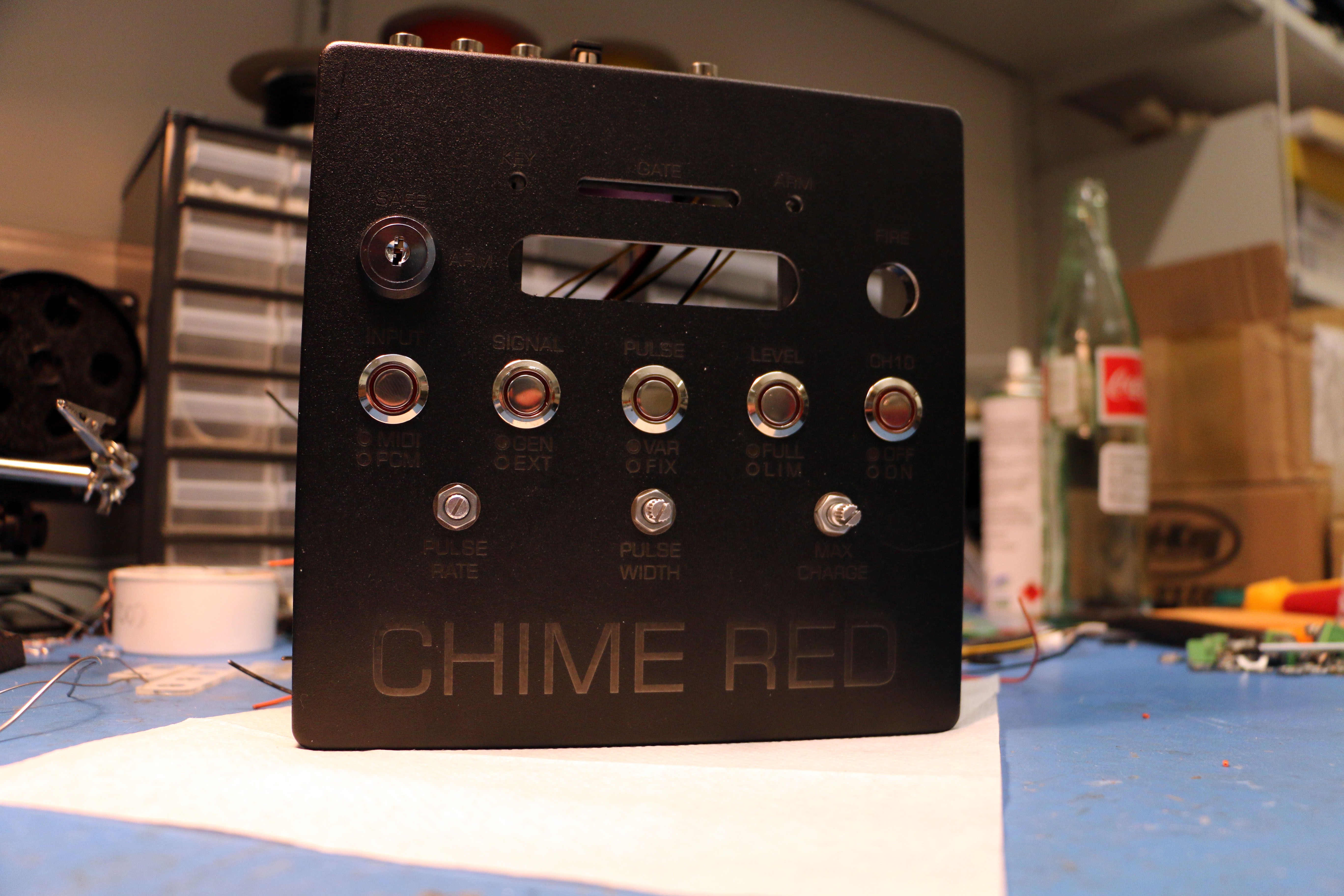
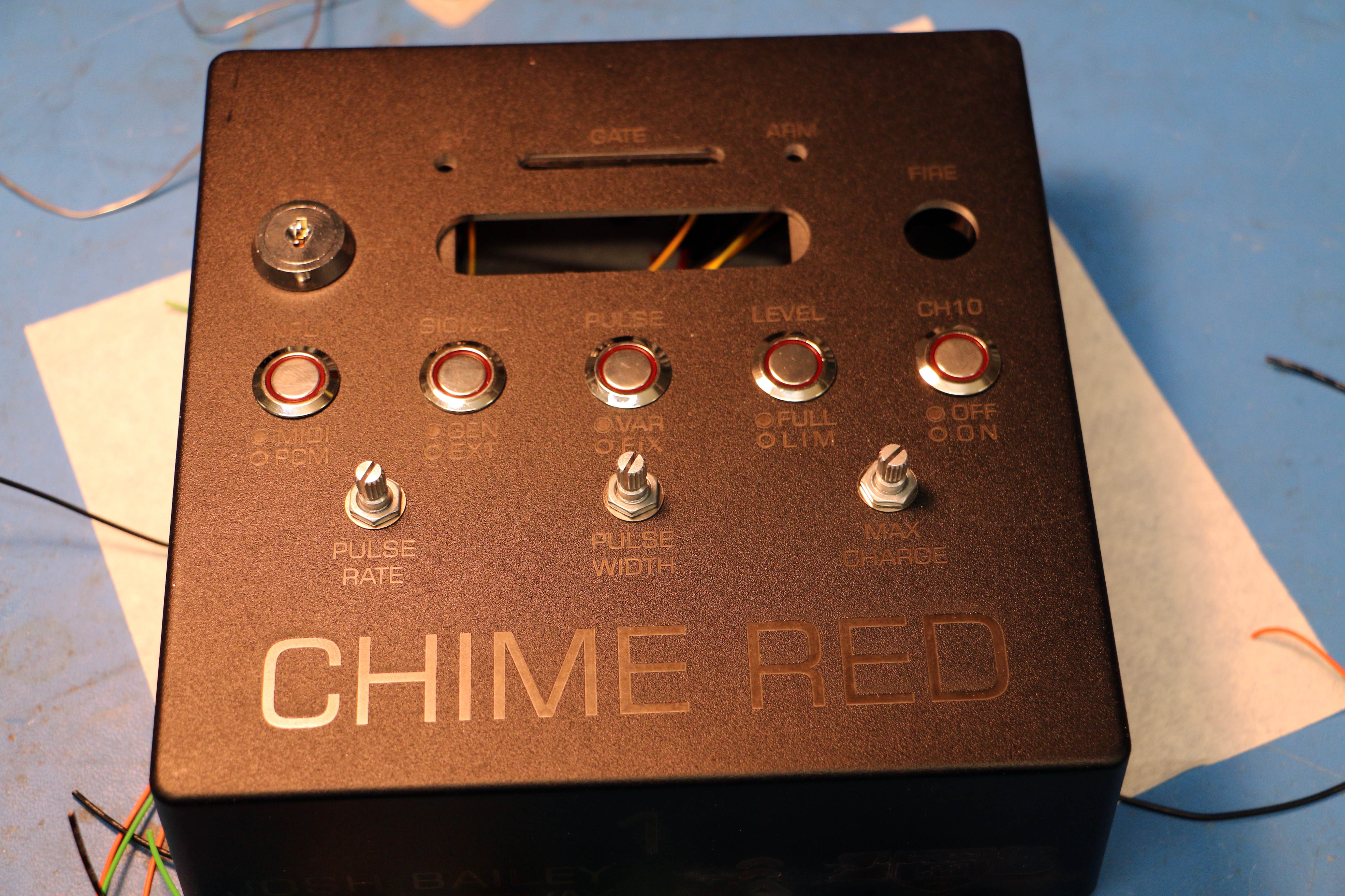
What the enclosure looked like with the shim and I/O installed
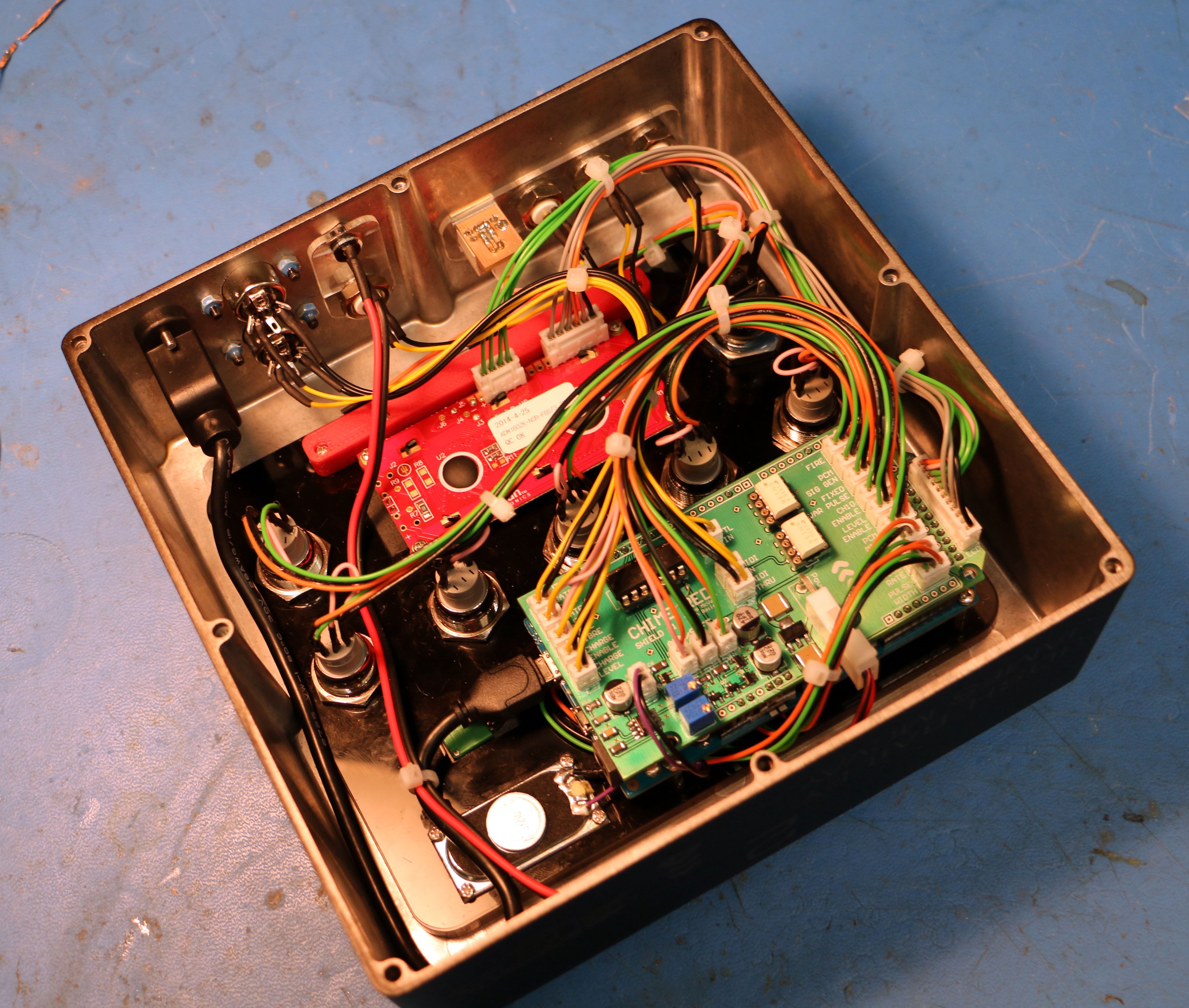
LCD and remaining components installed, with all the wires routed, crimped, and connected to the board.
The small, 3D printed red plastic component above the LCD houses the status LEDs (Keyswitch, Interlock and Gate)
Discussions
Become a Hackaday.io Member
Create an account to leave a comment. Already have an account? Log In.