Türtris
a LED matix build into a door to play tetris, Snake...
a LED matix build into a door to play tetris, Snake...
To make the experience fit your profile, pick a username and tell us what interests you.
We found and based on your interests.
I loaded up the hardware docu for 2 Versions (sorry this took ages):
V1 is the one is the exact one of the logs (might miss some bits and pieces)
V2 is improved to make the build a bit es tedious mainly by using WS2812B already soldered on a lttle PCB breakout board, which also holds a capacitor 8current stabilization) and a resistor (over volatage protection). The V2 is not testet by me in the Türtris configuration, but the Breakouboard are used in sisams social gaming cube and apear to be less prone to damage while soldering and less prone for failure in use (in the door some LEDs miss one color).
If you note something missing in the docu, make a version with other measurements or have any other questions/ suggestions, feelfree to ask.
Note: V3 is planned to use lines of read soldered LED stripes, but will require quite some rework, because the grid has to fit the stripe pattern)
I finally managed find teh arduino sketch back and uploaded it here.
http://mclien.de/files/tuertris/tuertris_sw.zip
Files of the design are to follow
Having glued all wires in place, I first solderd the main power "rails" in place, which is easy: just lay it crossed to the "V"shaped parts that will supply the LEDs and solder it in place. I didn't interconnect them to each other at this time, to be able to test each column separatly. First step is to drop a LED in each "box" from the rail, then I pressed them into the holes with a tweesers and flipped the whole thing over to solder them. Starting with the data connection:
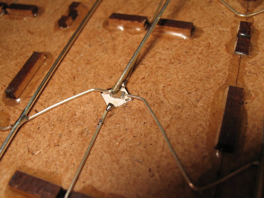
Here we see the data connection already soldered and the preperationfor the trickier one: SOldering the power connection with a capacitor of 3.2x1.6mm. While these little parts tend to stick to the liquid solder with more force tha the gravity will hold them down, one will need the ever missing 3rd hand (that is the one holding the 1mm wire pressing onn the cap from top). My solution is this: Just some piece of metal with a wire taped to it, so it hase some force downwars under which I place the cap.
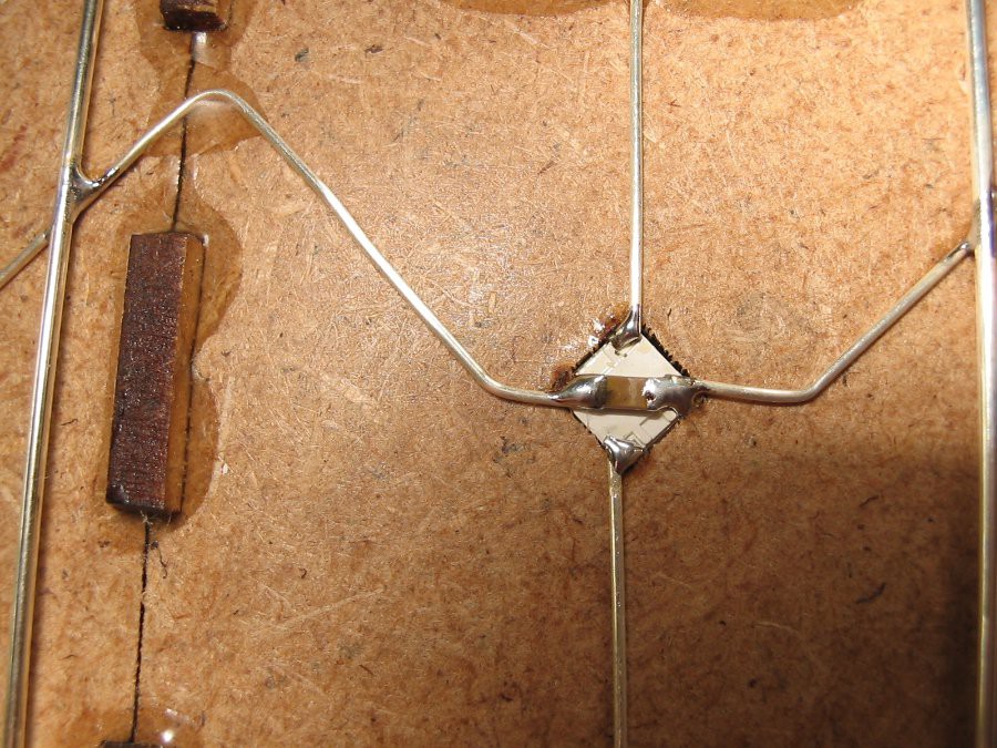
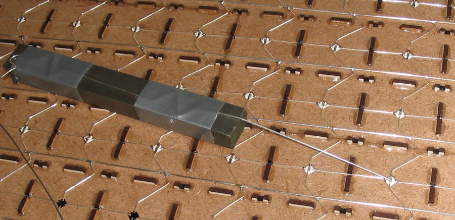
After some practise I found the right position of the positioning of LED, cap and wire (which I was able to bend in position, because gluing was done a bit away). So when nicely done I ended up like in the right picture. After each column I did a testrun with a little sketch (written by sisam) which just blinks through each LED with color white, which makes it instantly visable, if one color is missing. Non coloumn worked at the first try (I tend mostly to miss one solderspot or overheaded the LED and had to exchange it.
When all columns worked fine I closed the gaps in the data and powerlines and tested the whole thing with a new sketch which led 10 LEDs on run over the panel in each color (RGB).
I used silver coated copperwire for the electrification. Large amounts of that are delivered on coils, which means it tends to keep a curved shape. To straighten it you have to pull them a bit in lenght just to the point they start strech plastic.
From the pics on the last log you could see/read, that there are "V" shaped pieces of that. Being lazy AND kinda perfectionistic bending these parts manually without any way tho reproduce a similar shape to all of it, I built a little apparatus:
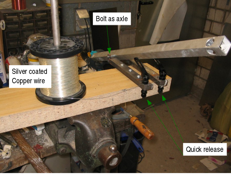
Mostly some spare/ leftover metal/ wood parts lying around and 2 quickreleases (normally used for seapost clamps on bicycles). The edges of the metal parts are rounded a bit (1-2mm radius) to prevent the wire from breaking throught notch effect.
After a bit trial and error I had the quick releases adjusted to the right force (you have to find the balance between the wire just slipping underneth the quick release and being stretched for straightnes) and could start:
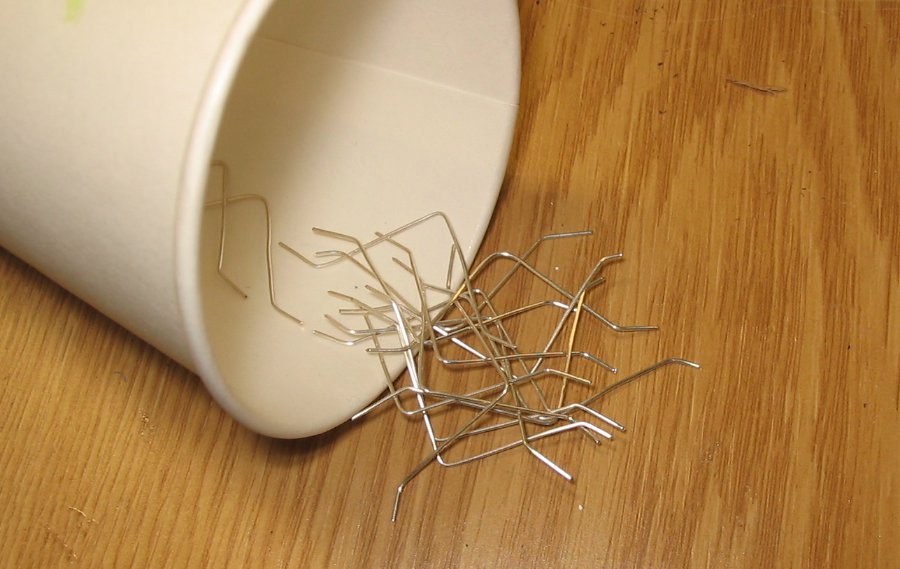
After some tests and repeats (roll up wire, close release, press down bar, open release, cut wire, repeate) I was good to do most of the parts blind while watching a movie (or two or three..). Afterwards I had to go through it again to get the correct and similar lenght for all. And soon enough I had more than the 315 I needed for the door:
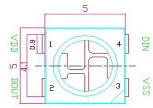
This is the pinout of the ws2812b LEDs:
quite nicly here is that at a 45° angle the power supply can be from both sides, while data goes "trough" it. Which led me to the following design:
This
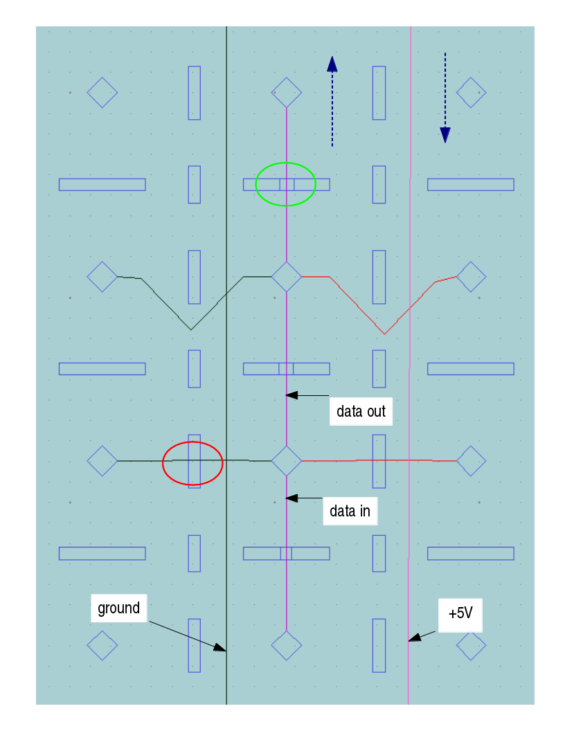
This is the view from the backside. on each LED we have power from the sides, which are supplied by the +5V/ground "rails". Data "flow" starts on bottom turns on top and goes down the next line of LEDs (blue dashed arrows), so the whole matrix is one single LED strip. As you can see I left a notch in each part for the data line (green circle), but not to the power line (was afraid to weaken the parts. red circle). So I went for the upper design, but will change the CAD data with new notches for the power wire aswell, to avoid the V-bended wire parts (see next log entry). Firstly I glued all wire parts from the packside to have all tips in place:
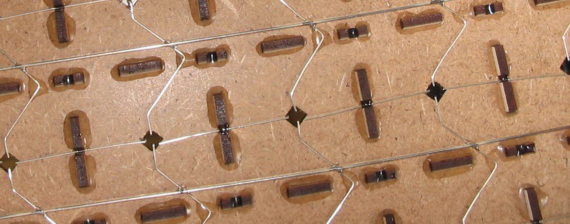
I glued the wire in place just by a spot of epoxy with syringe and blunt cannula. You can also see the gluing of the wooden parts, which were appied in the same way and only from behind.
So with alittle it of bending I had all wires in place. I then set the LEDs in place from top prevented from falling trought by the wire ends and holding in place for soldering by frictioin (holes are 5mm rectangele, solder pads stick out a little from that).
For lasercutting I prepared 300x600mm pieces of 3mm MDF (medium density fiberboard), which were leftover from another project. I think about 15 of them (I'll load up the set of dxf files once I sort it out). After a session of cutting I ended up with this:
As soon as it was decited we need a LED matrix, I started to design that thing on my CAD program. I use VariCAD, because some years ago this was the only affordable 3D program running on linux machines. So knew I would have a nice lasercutter at hand in our local fablab/open garage thingy (Die Werke). This way you can easily use rectangle shapes to make system, where the parts nice link together (holes for the LEDs missing):
The size of the cubic was tested with one of the LEDs some white cardboard aon a breadboard.
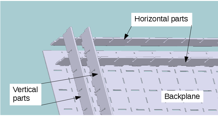
After designing that for the whole thing, it had to be cut into pieces that would fit into the lasercutter and still interlink nicely for stability reasons:
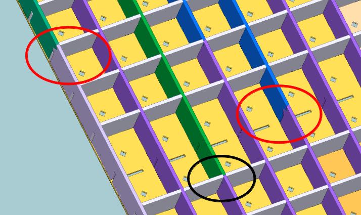
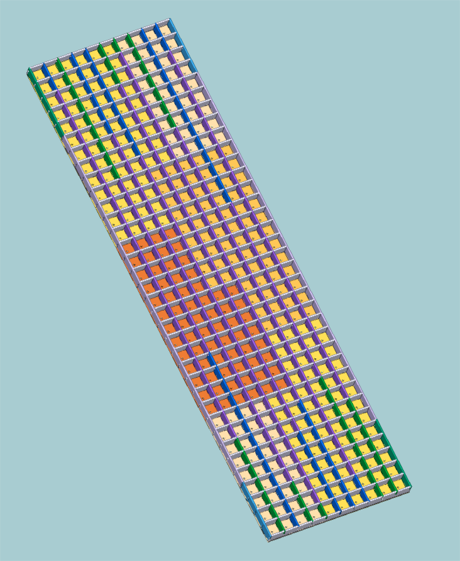
red markings show the link sction, black one how it's "captured" by the horizontal parts. Backplane is splitted in 5 parts, which interscet also. I made several links with different parts in lenght, so I could spread this weak points evenly in the construction. Here is the whole picture:
horizontal parts needed noe splitting
vertical parts: The way I designed them, there are two parts, depending whech end they end up (because the design of my splitting line dosen't allow flipping). So I made them even (blue) and uneven (green) to end up with one type on each end of the row. The backplanes have cutting lines which prevent them crossing the complete hight/width.
I will upload all CAD data (dxf parts already sorted for cutting on a 300x600mm bed and the uncutted parts as well as the 3D step data)
While rebuilding our house, it happened that the door of my sons room ended up at the other hinge side than planned. To my own supprise the only spare door was one with a glas window :
while this is nice in living rooms and hallways to spread some light, it's not as private and/or dark as you moght want it for privacy and sleeping. Buying a new door or appling a piece of wood instead of the glass was out of question, so we ended up with a quick duct tape and cardboard solution temporarily.
So we had some time to ponder a bit about which might a cool, nerdish or funny idea. That was about the time I stumbled over some cool coffetable LED build in ideas und alike.
Just a quick setup of the page, to have something to direct people to. It is because there are a lot of quiestions right now at the 31c3, which I cannot answer (too much dutx elsewhere), so this is the starting point.
I will update the information the days after the 31c3 with all the files for the lasercutting, photos of the building, code for the arduino and such, just stay tuned or conntact me.
I will be back after 31c3 for updates.
thanks for the interest
Create an account to leave a comment. Already have an account? Log In.
great project, and it was the first tetris project here that works on my led matrix. The arduino code is full of hardcoded numbers - to change the matrix size, after changing the values for matrixx and matrixy you also have to adapt the values in the for-loops.
do you have a github repo so we can contribute to the code?
Thanks. As to the git repo: Sadly not. But that is of course a great idea and you're right about the hardcoded values (I guess, was written by my son). Problem is, I'm highly unexperienced with git. I'll ask my son to look into it. Might be possible to set that up on my uberspace...
It is impressive that you soldered all the LED by hand without using a led strip. Can you tell me the price of the silver coated copper wire 1mm and from where you get it? I need some and I am cutting the lead of 1W resistors right now
Thanks. It required some zen patience, I can tell you ;-)
As for the supply: it was about 60 EUR/kg as far as I remember. But I have quite a lot of it on coil still (1,0mm and 0.6mm. I could snd you some, but that's kinda overdone from germany to thailand, I guess.
It's normally not sold for soldering but as a tinkering supply. Must be findable by searching for silver coated copperwire. If you have no success with that I can still send some to you.
Just looked up postage: It's only 3,70 EURO for 500gr to thailand, so not that expensive. Question is more how complicated the customs part will be on your side. Just let me know, what's easier for you finding the wire somewhere in thailand or getting it from me with customs to handle.
wow, thank you to inform about the delivery expenses. For the custom declaration just write it is a gift\sample. I have calculated that 20m of 1mm diameter would weight 0.14 kg that is more than enough for me. Can I transfer money using PayPal?
Paypal is fine in this case.
But doublecheck if you realy want 1mm diameter (that's quite thick compared to normal 1W resistor lead)
yes 1mm diameter is fine, 1w resistor is 0.7. I use it to keep a minimum distance between a iR reflective sensor and the piece to be detected.if the distance is lower the sensor doesn't detect. I can solder the wire directly to the PCB
Hallo,
Mein Sohn sah die TETRIS Tür auf dem Netz und jetzt fragt er mich, das gleiche zu tun in seinem Zimmer zu setzen.
Aber wie ich mit Arduino begonnen, ich habe Ihren Code kompiliert, und ich machte eine Montage mit einem Steckbrett und WS2812B LEDs. Problem LEDs sind in permance beleuchtet. Ich ging auf Arduino-Tutorials zu sehen, wie poussoires Tasten zu verbinden und ich umgestrickt die Schaltung.
Aber nichts funktioniert. Ist es möglich, den Anschlussplan der Arduino und Tasten zu haben?
Ein großes Dankeschön von meinem Sohn ( 8 jahre),
Very cool project, inspired me to build this:
https://hackaday.io/project/11064-raspberry-pi-retro-gaming-led-display
Yes, of course. I'll do my best to get it uploaded together with design/ lasercutter parts this week. (We have a makerfair comming WE here, so I might not get it done, but I'll realy try to)
Thanks for the sketch ... im working on the hardware part at the moment ...
I'll try to have at least one version of the hardware design uploaded within 24h .
Hi mclien,
im looking at your drawing "wireing" - is it true that the start of your data flow is at the bottom right (Front view at the glowing Pixels).
So the data flow goes from bottom right to the top, goes down and up again until the top left position is reached?
Nearly. the pics are from the backside of the door.
So data flow starts bottom left from the glowing pixel boxes (that is bottom right from the wiring site). and the up, down the next row until top right is reached (top left from the wiring site).
[ sorry abou the delay in the hardware details, got drowned in the Makerfair work, tomorrow is my next goal to get is]
Wow, this looks really slick. The way the glass-blocks light up is *perfect* for Tetris.
Seen it on a congress. awesome idea. going to assemble something like it on my ceiling. to play tetris, snake, and other block/color games
I dont get why do you need capacitors here? Why not just use preassembled strip like
http://www.aliexpress.com/item/100-Pcs-Hi-Q-12mm-WS2811-Full-Color-Pixel-LED-Module-Light-Waterproof-IP68-DC5V/1869247254.html
Capacitors are needed for stable/even voltage (and are normally fitted on those strips, too).
The rest is a matter of space. the thickness is limited by the door and for the final build, when the missing diffusor is istalled you want to have those little boxes a deep as possible for nice distrubution of the light behind the diffusor glass. That leaves you to spare as much room on the backside as possible, which at least at the point of building to me seems to be the choosen way.
The other kind of strips (the flat ones on the flexible PCBs ma be a way, but the you are limited to a certain distance between the LEDs)
Become a member to follow this project and never miss any updates
 Sarah Petkus
 Supplyframe DesignLab
 marciot
 Angela Sheehan
Congrats on the neat wiring job. I love how you built your own tools to bend the wires.