MasterOfNull
-
Old Milwaukee here I come
09/28/2016 at 12:01 • 0 commentsMilwaukee was a disaster.
I thought I had to scavenge some parts from M1 to make M2 work, so M1 did not make the trip.
M2 then failed as a bad step-stick was pulling down on the 3.3v rail just enough to make everything freak out. It took me until half-way through the second day of the show to discover it as it was acting like a software issue.
When I finally found the bad step stick and replaced it, I had two different paths in Machinekit both driving extruder heat. The hot-end suddenly turned on and cooked itself before I noticed it.
Some flailing then ensued in an attempt to resurrect it, but I could not adequately cool the hot-end without my machined cooling channels. PTFE does not conduct heat well enough to be a heat sink even when filled with water. I pretty much finished it off with my flailing.
Game Over.
Oh yeah.. I built a new one!
![]()
Six color, lighter combined end effector/print head, counterbalanced stepper carriage, simpler construction, and gorgeous.
-
Milwaukee here I come
09/02/2016 at 00:51 • 0 commentsThe M1 is getting a makeover for the MilwaukeeMakerFaire.
Designed a smaller delta platform with more standard parts, this time making sure it will fit in my trunk.
So much to do...
-
Sleep deprivation
06/22/2016 at 05:42 • 0 commentsBeen busy with other responsibilities, but finally taking the time to share the 'latest'.
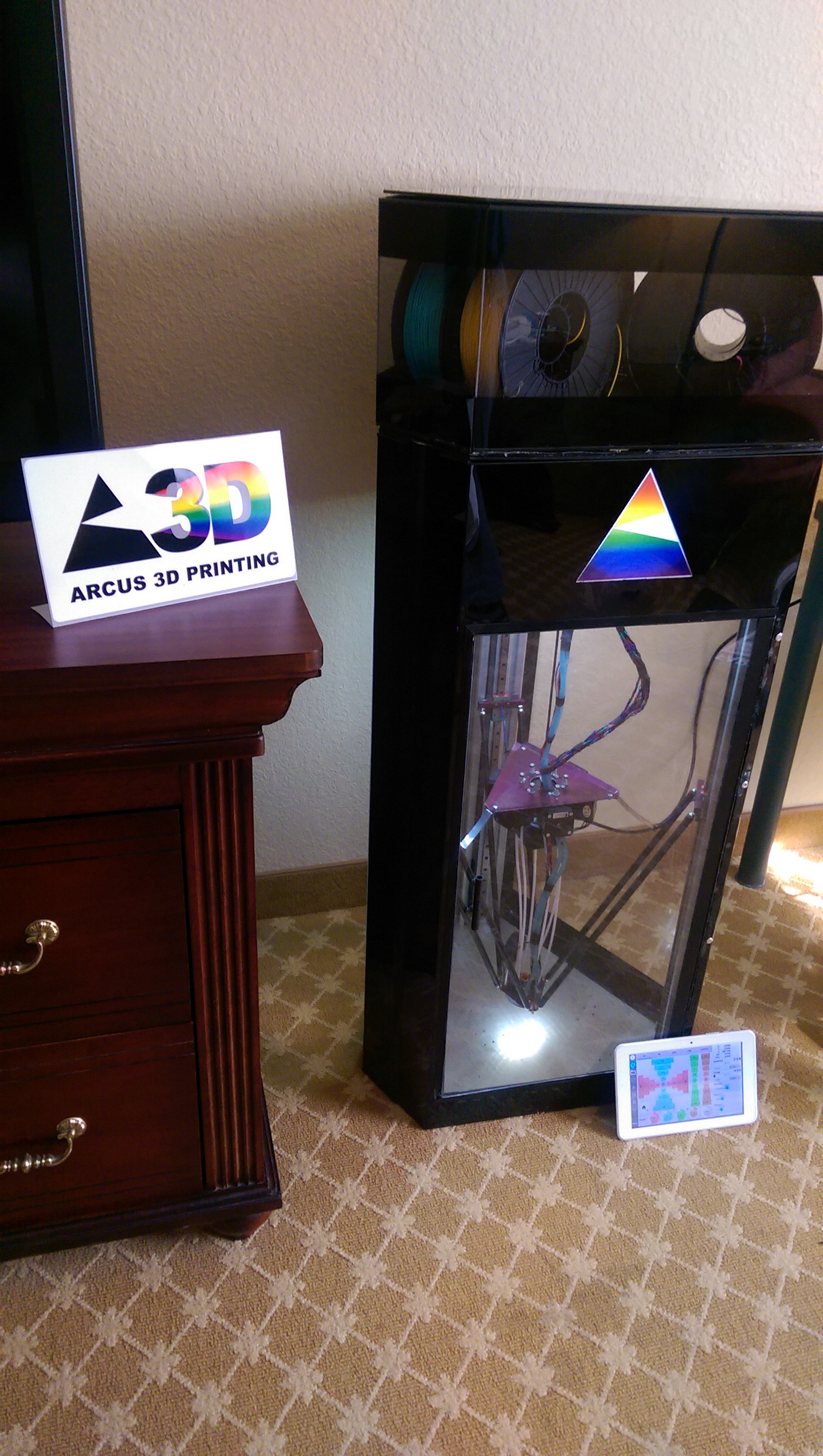
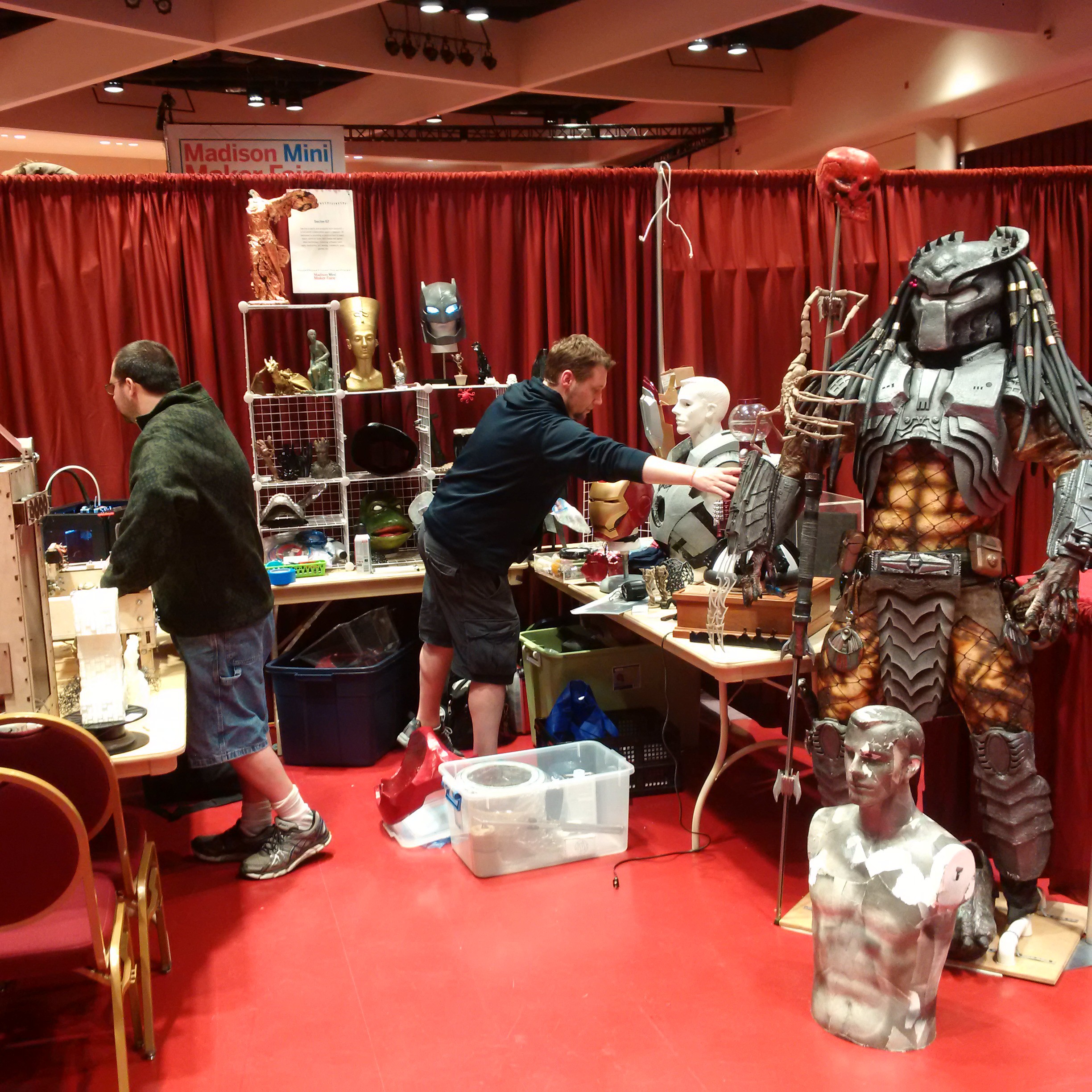
I had signed up for a space to show the printer at the Madison Mini Maker Faire. I was right next to Sector67.
![]()
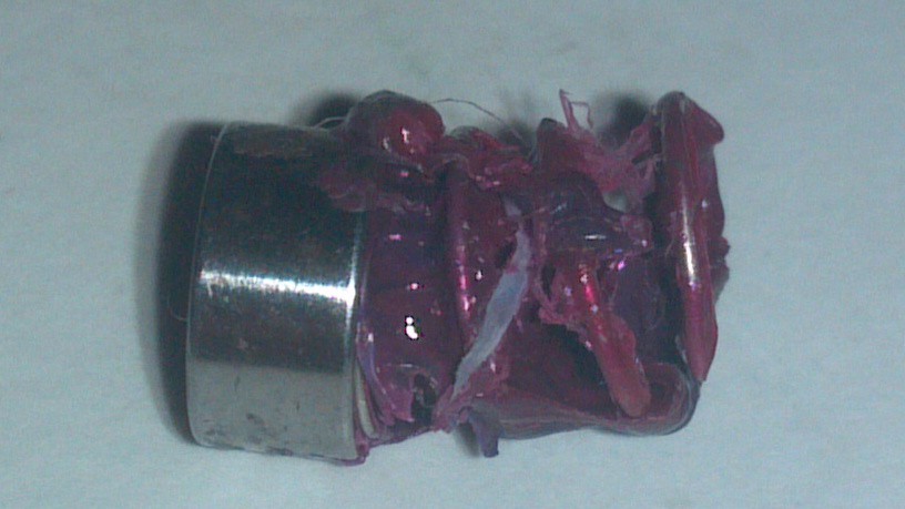
Being generally short on time, the evening prior I attempted to correct a leaking feed tube.
Prior to this, it was usable. Afterwords...
![]() The date on the above photo was 10:20pm the night before the faire. Complete disaster.
The date on the above photo was 10:20pm the night before the faire. Complete disaster.The tubing is press fit and the sealing is simply from tight tolerances. Re-using the old print head was not an option.
So... I machined a new one. That night. From scratch. Right after pressing it together, all the bits went into a box and the box went into the car. I then drove the 2.5 hours it took to get to Madison and made it there by 9am. I assembled the brand new, never tested print head on-site and was printing by about 10:30.
It worked. It didn't leak. But..
It was completely un-calibrated and I could only print in the very center of the bed.
My stepper current calibration was totally messed up from banging it about. I was skipping on some, and burning up on others.
I didn't put enough water in the cooling system as I filled it from a borrowed water bottle from the next booth.
I failed to turn the cooling system on at one point, and melted down the print head and overheated the steppers enough to melt the PLA into the feed gears.
It kept jamming up when I printed white.
After the drive back from Madison, I deduced why the latter was happening. In the PLA I didn't bring with me to Madison was my roll of white. So for the entire show I was printing with 4 rolls of PLA, and one roll of white ABS.
Sleep deprivation sucks.
-
Bye bye blobbies
04/15/2016 at 01:29 • 0 commentsI figured out why I was getting blobs at layer change regardless of retraction.
The M700 command which sets filament diameter for velocity extrusion appeared at the beginning of every layer/area. It was not set to be 'synchronized' by default. The trajectory planner can only handle 'synchronized' commands.
That means every M700 command would break path blending, causing a pause to occur while the trajectory planner started path blending from that point on over from scratch.
It also appears way more than needed, essentially setting the filament diameter the same, over and over.
I will need to fix this in the custom branch of Slic3r to do it right. In the mean time I've just set all M700 commands to run synchronized. There are probably scenarios where this wouldn't work right.
Spun two of the liners while polishing/reaming them out in the new print head, so it leaks. Fix is another new hot-end. This weekend probably.
Edit: Turns out I was wrong and the real reason I was getting the blobs was related to my code, not the stuff in Slic3r. Same underlying cause, with the trajectory planner having to recycle, but it was because I was using a letter reserved for other purposes when I defined my M163 gcode handler. Oops.
-
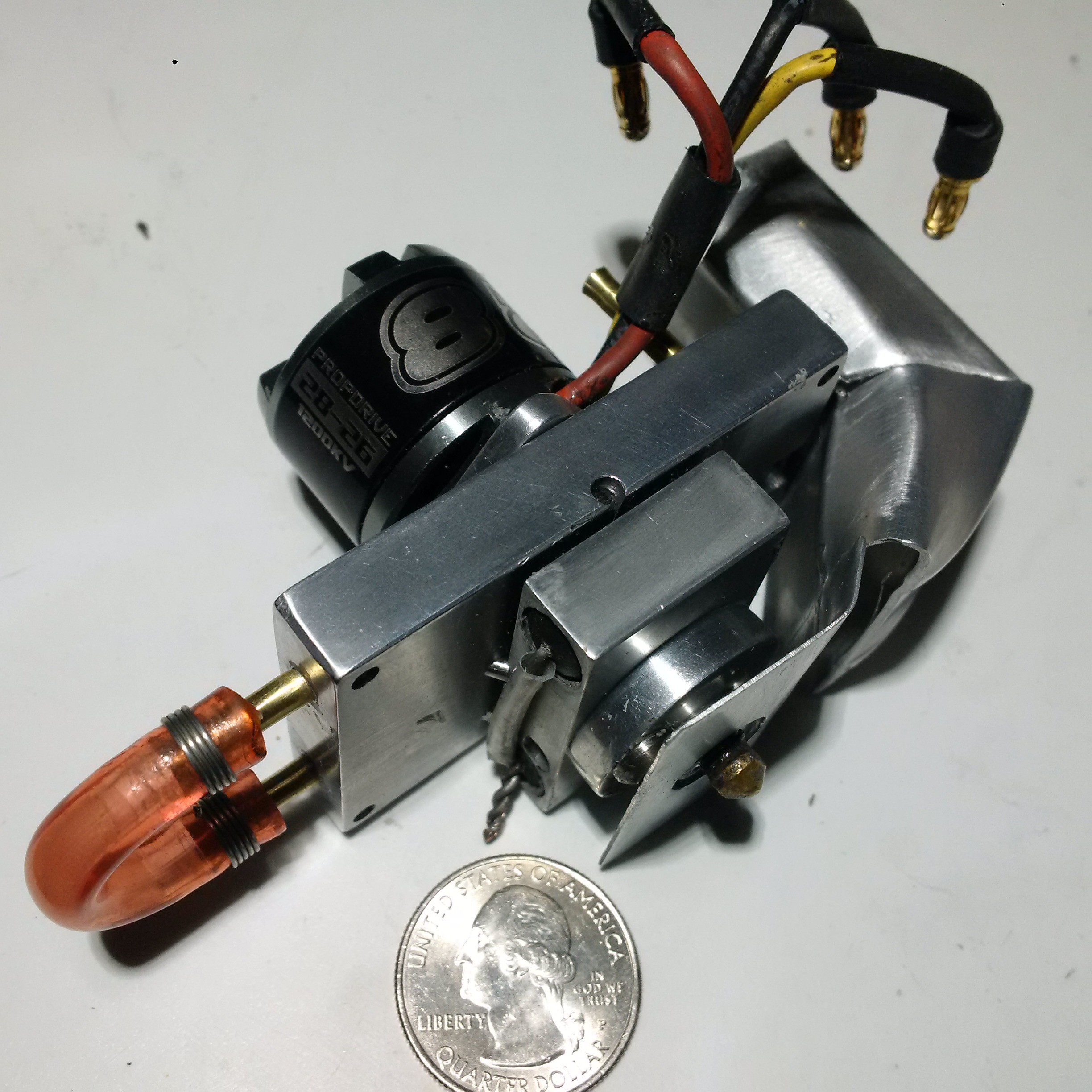
Print head v10.1
04/05/2016 at 22:45 • 0 commentsNew stainless got here. Switched from 304 to 316. So far i'm liking it.
Slightly thicker wall stainless, so I had a little room for adjustment of my holes. Changed the angle slightly so I could Increase the clearance between the hot/cold end by 0.5mm. Much easier to work with.
Polished the *inside* of this one...
The print head struggled to maintain temps > 230C with the fan on full while it was close to the bed.
Made a new air conduit-deflector-shield-thingy.
![]()
-
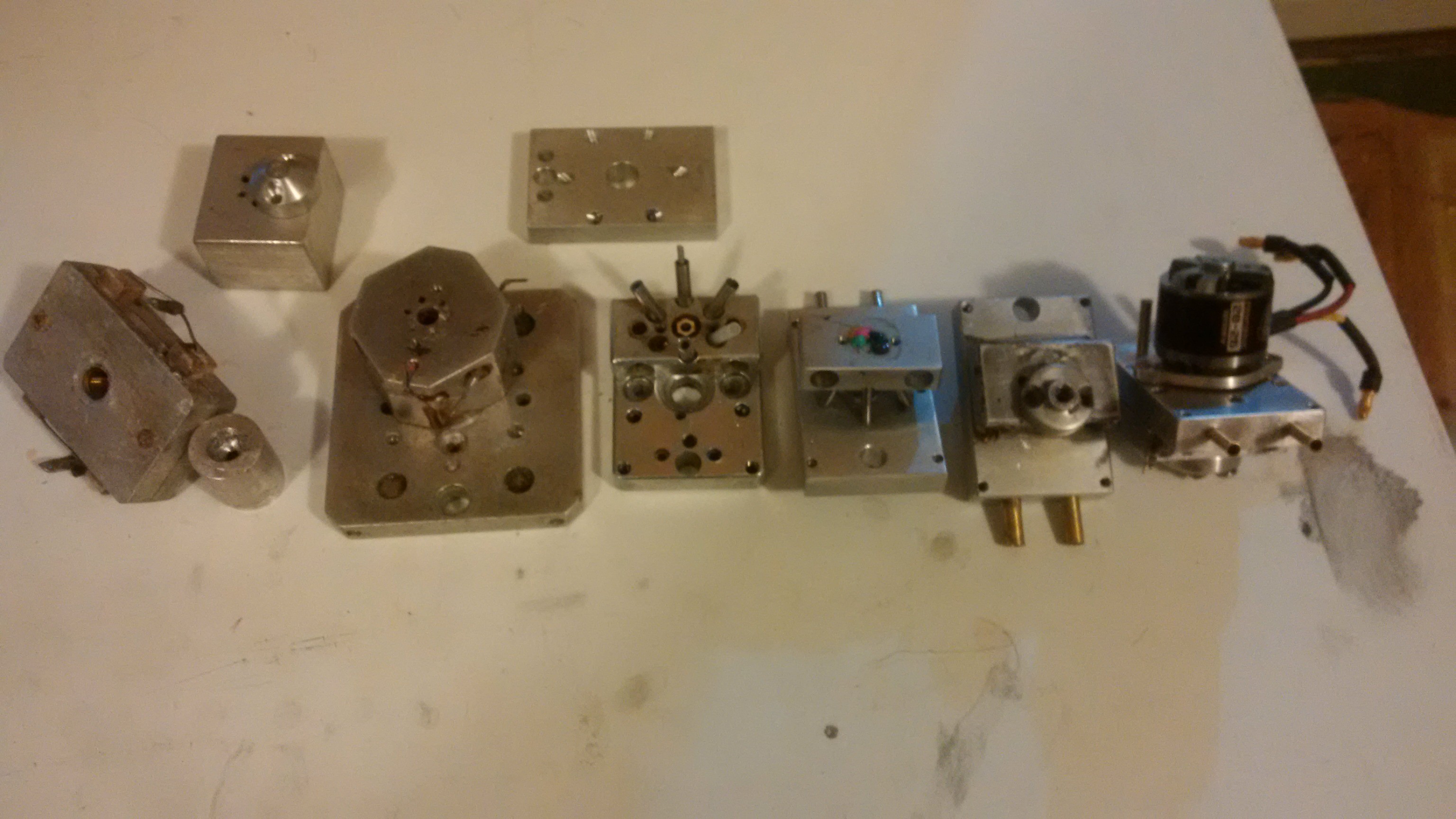
Evolution
04/03/2016 at 01:47 • 2 commentsGot the latest print head torn down, cleaned up, and ready for my replacement stainless tubing to arrive.
In the mean time, here's a pic of the surviving prototype print heads, which didn't get recycled to make new parts.
![]()
-
Print head version 10
03/31/2016 at 02:06 • 0 commentsBuilt another print head.
Reduced the cold/hot transition to as small as practical with this design. It's about 3mm now.
Got really good tolerances on all my parts since I did some work on the drill press. By far, this is the most accurate nozzle I have made.
Press fit the stainless tubing liners. It went in hard. Too hard. Some crumpled under the pressure.
Had just enough stainless to try those again. Got them in, but not to full depth.
Drilled the mounting holes for the nozzle and tapped them out, after assembly this time. That was a mistake for this version as I only have 1mm of clearance between my cold/hot end. I screwed the tap in too far and it impacted the cold-end, which un-seated some of my liners. Bah.
As I had just consumed the remainder of my stainless tubing, I put it in a vise and pressed it back together hoping for the best.
I started it up and loaded 5 colors. Primed it. My nozzle was almost completely blocked with machining garbage (I found out later), so the extrusion literally blew out one of the feed tubes. Cool looking failure though..
![]()
After cleaning, it works, but now leaks around 2 of the tubes. Removing/re-seating the tubing is not possible and will destroy it. More tubing is on the way.
-
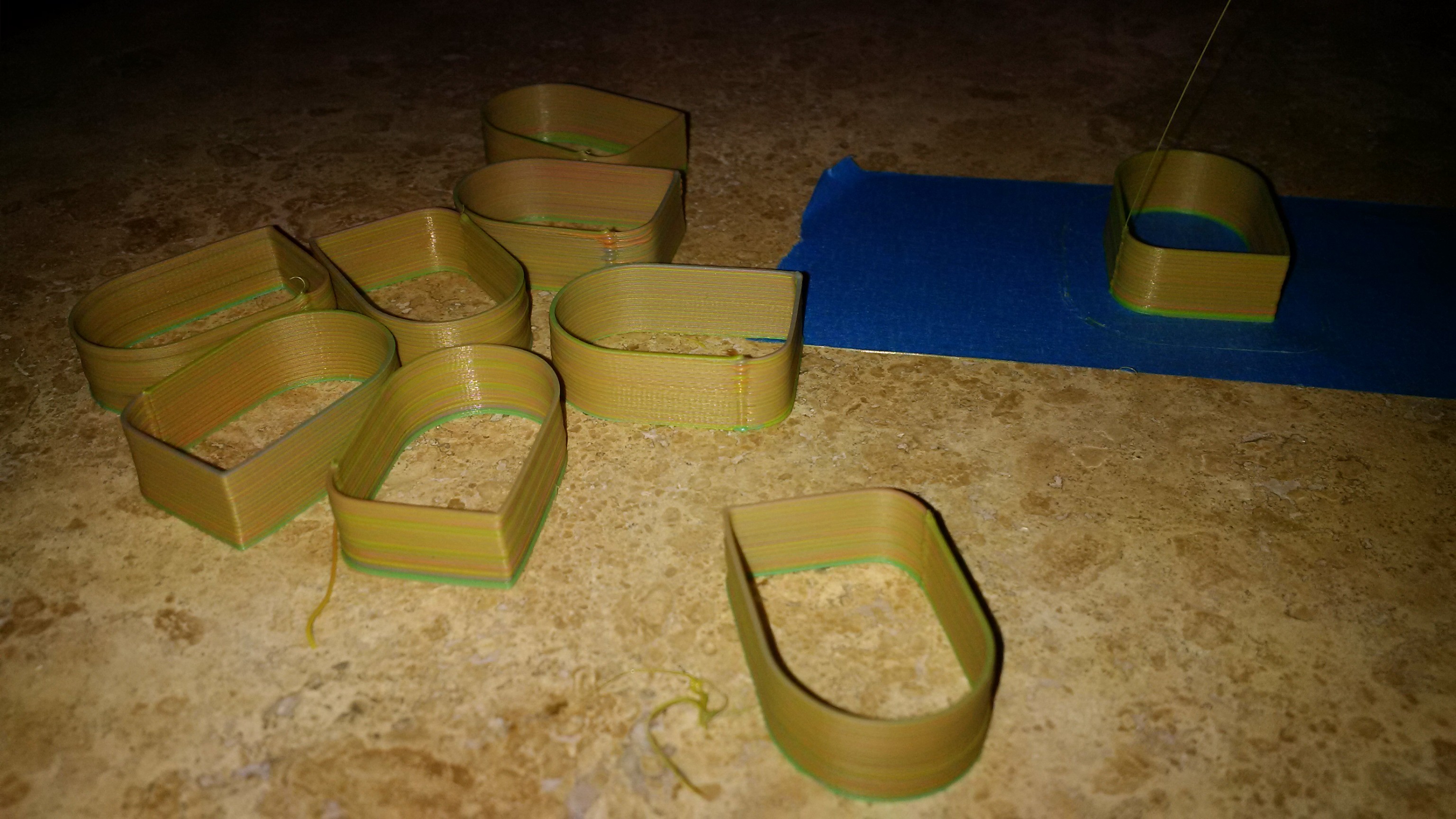
Testing, testing, 1, 2...n
03/21/2016 at 05:45 • 0 commentsPrint head is back together after the self induced meltdown. I added the two changes I mentioned (better seal fit, and a backup seal with a path for leaked filament) to the existing print head. Welcome to version 9.1.
I immediately used the leak port as I didn't tighten my set screw and therefore failed to spring load my seal properly the first time. Cleanup, another new seal (as I damaged it on removal), and another assembly and I was back in business.
Testing got serious today with a single wall test print. Printed about 30 of these.
These are the last 9, about when I started to get everything dialed in as best I could.
![]()
These are at 0.2mm layer height, printing one color per layer, using cyan, yellow and magenta only. White just made it lighter, and black made it look like mud at 0.2mm. At 0.35mm, black was nicely contrasted. Black takes just about the whole layer on one of these to purge as the saturation is so much higher than the CYM I have.
I started to double the bottom layer for better adhesion as my bed wasn't exactly level, and so I didn't have to keep changing my tape.
At that layer height, the only time you can really see the color is if a filament drive skips. You have to look really close, but every layer is a new color. I still haven't changed my damaged stepper drivers, and as a side effect they run pretty hot so sometimes I have to give those a push.
I still get a little bubble where I change layers, with or without a color change. As all extruding is controlled by the velocity extrusion calculations, and not E values, I'm looking at the code for clues.
Retracting while feeding the old, changing the color code, and then un-retracting the new resulted in the fastest color changes. It also made the layer change bubble bigger. More retraction doesn't fix it. I'm assuming the idle filament continues to expand slightly while retracted. I can *probably* fix that..
-
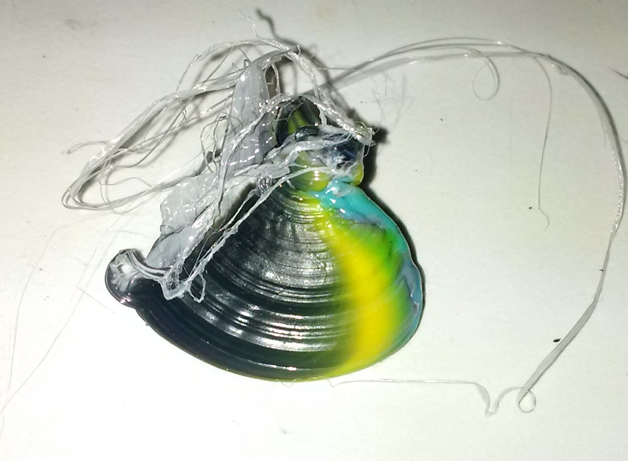
Speed kills
03/18/2016 at 00:52 • 0 commentsBeen printing that logo for the past 2 days tuning the printer.
Mixer speed was gradually increased.
Today I turned it way up...
It turns out you can print *really* fast with an impeller driven print head even with a small nozzle and a low layer height.
I re-sliced my object and turned everything up. That wasn't maxing it out, so I also had my feed-rate at 150% and I was still not stripping my filament. Converting velocity extrusion back to normal E numbers still eludes me, but just grabbing it, I was pushing about 7/8in per second to a .35mm (.4mm measured dia, after die swell) nozzle.
About 20 minutes into my third, large print running it like this, the impeller motor started to loose speed. I knew right away what had happened. The seal had eaten itself.
I'm assuming the increased pressure to the nozzle caused more force on the seal. When I took it apart for a postmortem, the seal was completely gone.
It was awesome while it lasted..
Edit: On later inspection I found the seal in the mass of leaked plastic encasing my spring/thrust bearing. It had extruded itself through the gap around my mixer shaft and was now a long ribbon.
![there you are...]()
Extruding shaft seals is a problem I had already solved previously, but I had not needed to implement yet for this version.
Back when destroying shaft seals was commonplace, I also gave the plastic a better place to go than into my bearing. I'll be bringing that design back as well.
Perhaps I can keep some of this new found speed..
-
Visualizing weighted mixed-material gcode
03/13/2016 at 10:41 • 0 commentsStarted to manually add the M163 codes I use to control filament weight values into some gcode.
That sucked.
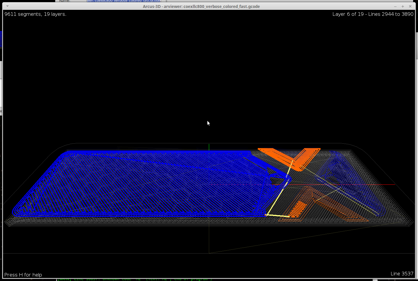
Found a suitably hackable python based gcode viewer called yagv and adapted it to speed this process up for more complicated objects. It lets me visualize the resulting mixed filament, and quickly find the next location in the gcode file I need.
I assigned each filament an RGB value in config.cfg
- [255,0,0] - red
- [255,255,0] - yellow
- [0,0,255] - blue
- [0,0,0] - black
- [255,255,255] - white
The viewer reads the gcode file tracking the changing filament weight values, combines them with the defined filament colors, and renders the resulting mix per segment.
Setting a weight of 50/50 for a red/white filament would end up being [255,123,123] and render pink in the interface. Close enough.
Right mouse button + drag moves forward/back in time simulating the extrusion, or you can use a wealth of keyboard shortcuts.
An interactive gvim session is kept in sync with extrusion playback so you can go directly to the line being rendered with a mouse-click.
Pressing R, saves your changes in gvim, and re-draws the object calculating the new mixing for the object.
![]()
So I'm still modifying the gcode in a text editor and adding my color weight information manually at this point, but this just got a whole lot faster.
I've added everything I've needed as keyboard shortcuts. You now can edit the entire file in the one interface, without your fingers leaving the keyboard. (provided you setup your colors as macros in config.cfg)
The cool thing about this approach, is I could load up 4 different shades of blue and a pink, and still get an accurate estimate of what it would look like because the filaments slots aren't tied to a specific color. The interface just shows the weighted sums of the result.
My code is now up on Github for all experienced python programmers to scoff at. :)
Arcus-3D-M1 - Full Color Filament Printer
Active mixing, fused filament fabrication 3D printer.
 The date on the above photo was 10:20pm the night before the faire. Complete disaster.