MasterOfNull
-
A step back.
12/16/2015 at 03:41 • 0 commentsMachined a new impeller. Actually, machined three new impellers. The third one turned out.
Managed to lose the <1mmx2.5mm stainless steel collar I had so meticulously machined to fit my impeller shaft to help with sealing the latest version. It kept spinning on the shaft which defeated it's purpose. The only reliable way I found to keep it in place with the temperature shifts it will experience was to get a perfect friction fit while my collar was torch hot. I made a tool to remove it without damage and popped it off so I could use to it on the new impeller.. I heard it hit the floor. It's now keeping all my un-matched socks company somewhere. I've decided against making a new one and I'm going to try a larger PTFE seal to take up the space. PTFE is easy..
When I tried out my new impeller, it exhibited exactly the same issue as the old one. It contacted the walls of my mixing chamber intermittently when spun.
Turns out the old impeller was probably fine. I had just failed to clean all the melted plastic out of the mixing chamber. The last thing I printed was in clear and as I'm running out of the high-temp thermal compound, I didn't burn it out like I usually do.
Duh.
I've been pushing for smaller and smaller mixer impellers as the smaller the impeller, the smaller the volume of mixed filament, and the faster the color changes will be. I still get perfect mixing, and I'm now at ~2mm for my mixer..
I've gone past the limits of what I can reliably do in my garage, and I have been making up for it with iteration. Example... when I turned the last new impeller shaft, I had to let my thumb drag on the chuck to keep the play in my bearings from ruining the part.
So, I've decided to take a step back. When I eventually destroy this version, I'm not going to sweat building it bigger so I can machine the parts on the first pass with what I have to work with.
Once I can afford to replace my aging tools, then I'll see how small it can go.
-
Impeller drive x 2
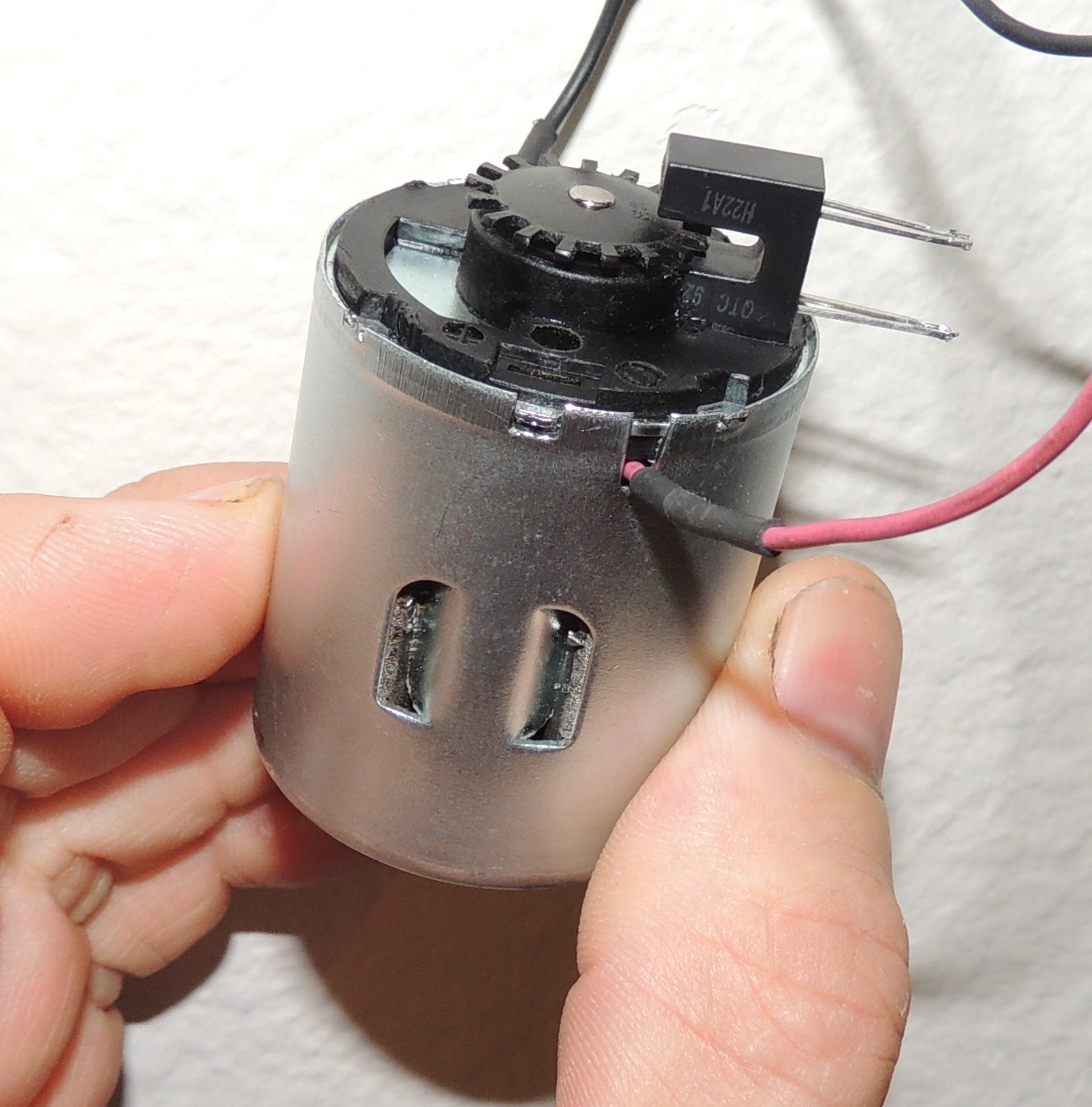
12/13/2015 at 22:19 • 0 commentsFinished a new impeller motor.
Added optical feedback. Used an old mechanical mouse wheel with every other tooth removed, and machined a new shaft coupler.
I must have damaged the bushings along the way. It no longer spins freely. I wasn't liking how heavy it was either. I trashed it.
![]()
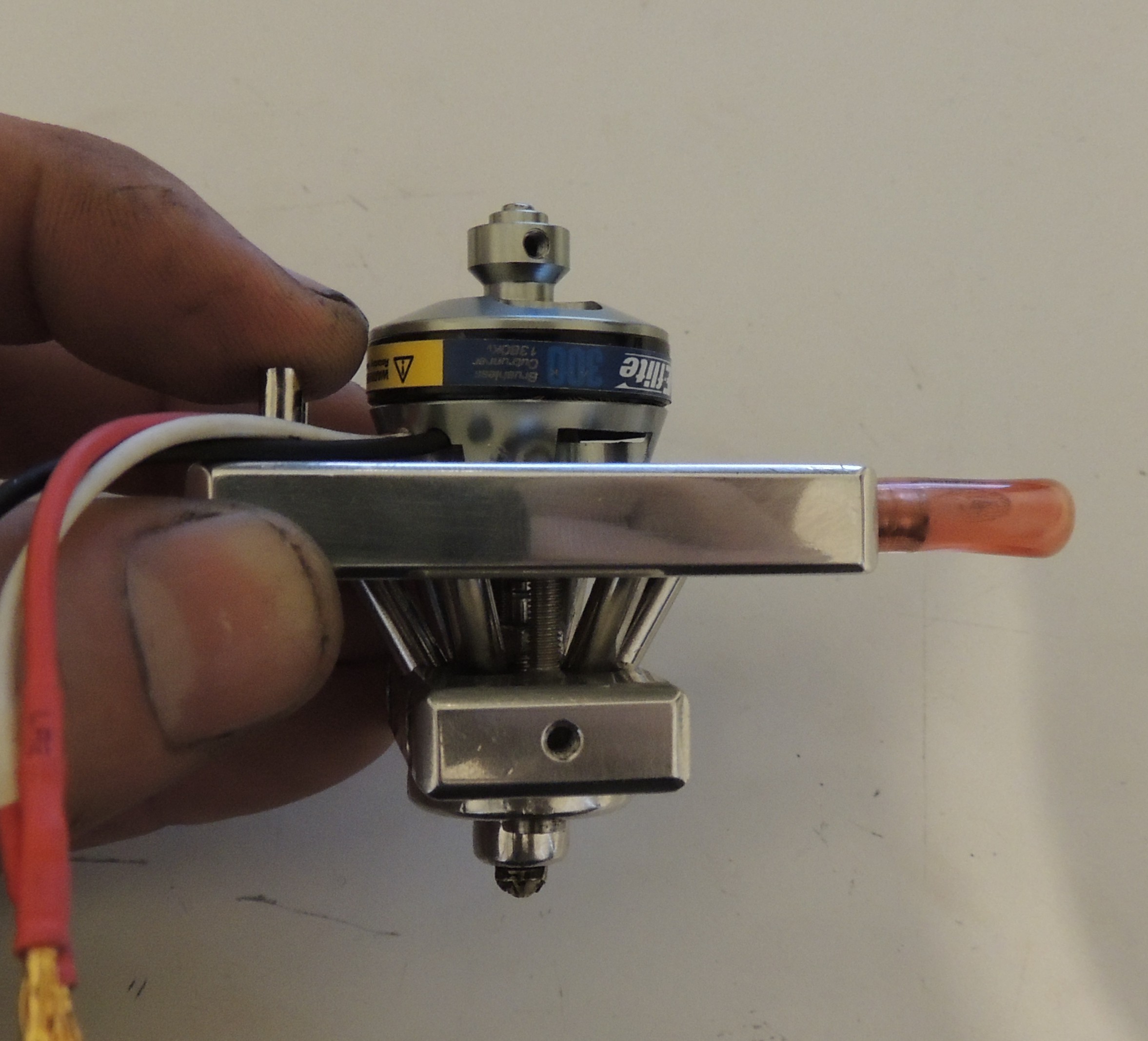
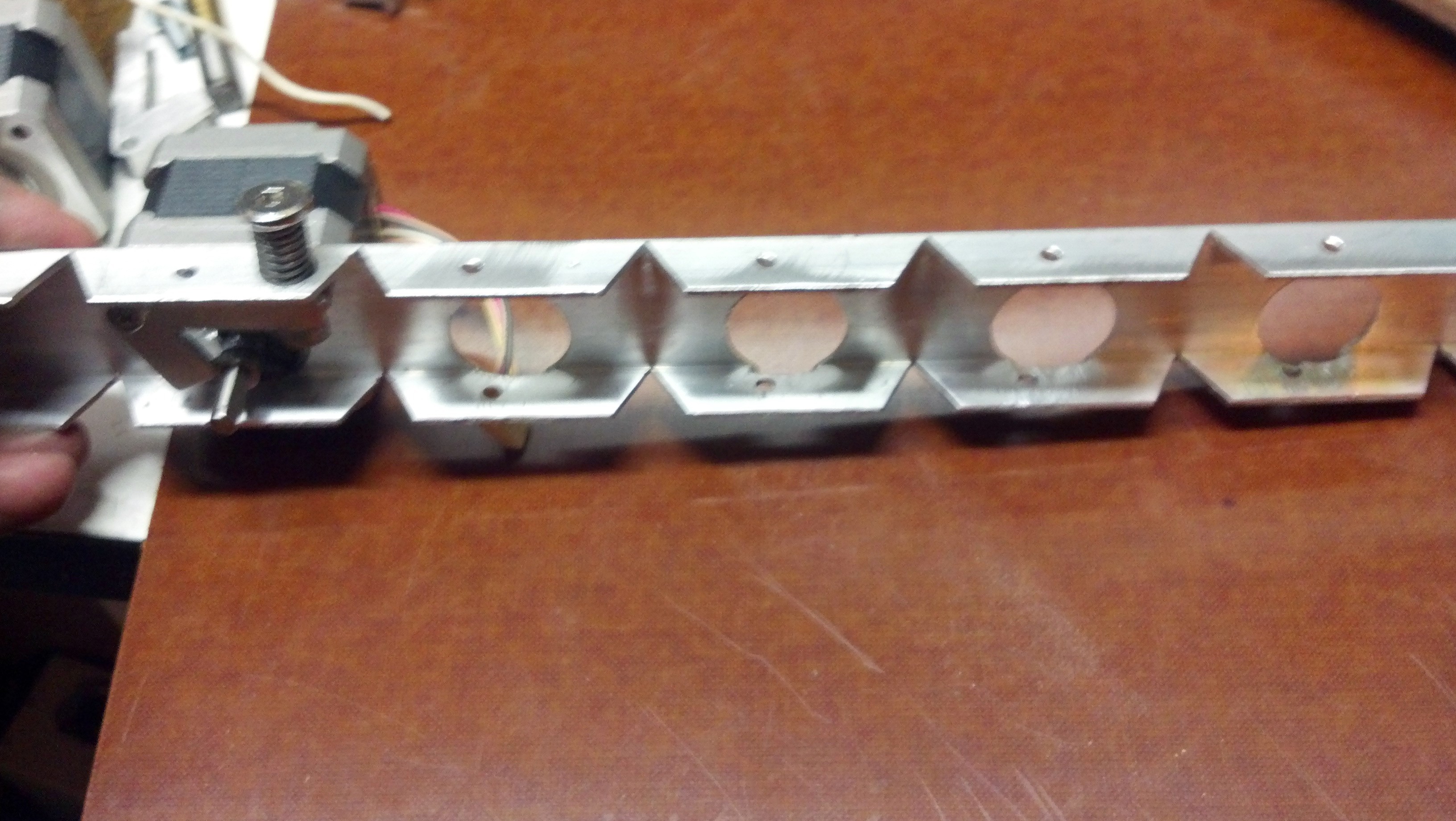
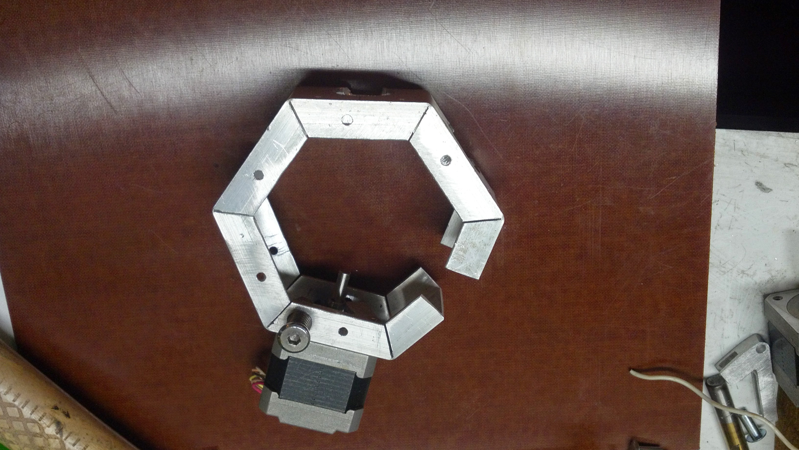
Decided to go a different route.
Modified the motor mounts and put a quad copter outrunner on it. It is thermally coupled to my water cooling plate so I should be able to run it pretty hard with no airflow. Problem is, without any give in the mounting of the motor now, alignment of the motor and impeller drive is critical. It's very close, but needs some tweaking.
Re-machined the hot end to cold end screws to now terminate into the cold end plate. Previously they went directly into the motor.
![]()
Figured out the timing I need for driving the ESC with my Beaglebone PWM.
Basically, run my PWM at 100Hz (which it already is) , and then setting 10%-20% duty cycle will generate the 1ms to 2ms pulses the ESC is looking for to give 0-100% throttle. For my particular ESC, setting the throttle range will be accomplished by powering it up at 20%, then reducing to 10% within 2 seconds. The rest of the ESC settings look good for my 12v source. I'm hoping it doesn't 'lag'...
Somewhere along the line I also managed to bend my stainless impeller shaft. Need to machine a new one.
-
Impeller Death March
11/11/2015 at 07:11 • 2 commentsPowered it up with my new seal in place, and I just succeeded in burning out at least one phase of my impeller drive motor. It still runs if I remove the load and give it a spin.
My seal was too tight (at least at room temperature), so the motor was stalled and it released some of the magic smoke.
The magic smoke is rather hard to get back into things.
I've stalled it before for much longer without burning it out. It was a 15v motor and I was only running it at 12v. Guess that didn't save me this time.
I have a slightly larger replacement. Well, the 'can' is larger at least. That's probably a good thing as I believe I was running the previous one near it's torque limit. Still 5 phase, same voltage.
I'll need to machine a new shaft coupler and modify the mounting a bit as the new motor is metric. This also eliminates the last non-metric part in my print head. Perhaps it's fate. :)
Now would be a good time to add some feedback so I know if it stalls. I had already wired the optical input which would make my cheap DC motor into a proper servo, but I never actually plugged anything into it. I have also not implemented the software feedback loop, set limits, or actually wired the other end up to the Beaglebone.
I could also use the applied PWM duty cycle versus the resulting RPM to roughly calculate the viscosity of what I'm mixing if I'm smart... Not sure what I'd do with that, but hey..
-
Let there be Full Color
11/08/2015 at 05:58 • 0 commentsWell not much has stayed the same since my last update.
There came a point where I decided that I wanted to attempt to produce a full color filament printer, and this project went from 'scrap pile, hey it works' to completely insane machineshop time suck.
I scrapped the old ATX PC mobo and replaced it with a Beaglebone Black. I simply didn't have enough I/O on the PC to take it any further. Nothing in the Arduino world had the horsepower I needed for this, but the Beaglebone gave me everything I needed and more:
- A Debian Linux box running on an 1ghz ARM processor
- 512mb ram.
- 4gb onboard flash. SD card slot, which is bootable
- Hardware floating point acceleration
- Hardware 3D acceleration (with some work)
- Ethernet, I2C, SPI, USB master and slave ports, rechargeable battery management, HDMI with audio, 6 channels of ADC
- and most importantly... 2 programmable hardware real-time processors running at 200Mhz, tied to 68 software configurable I/O pins.
It's an engineer's wet dream. I really don't understand why everyone isn't using this thing.
The Beaglebone has turned out to be nearly perfect for this project. It can easily handle driving the 8 steppers, 6 channels of pwm, compute the extrusion required in realtime, and still run at less than 30% proc. However... it is relatively delicate electrically compared to an Arduino. I have fried 2 of them through carelessness and borrowing it for various other short-term projects.
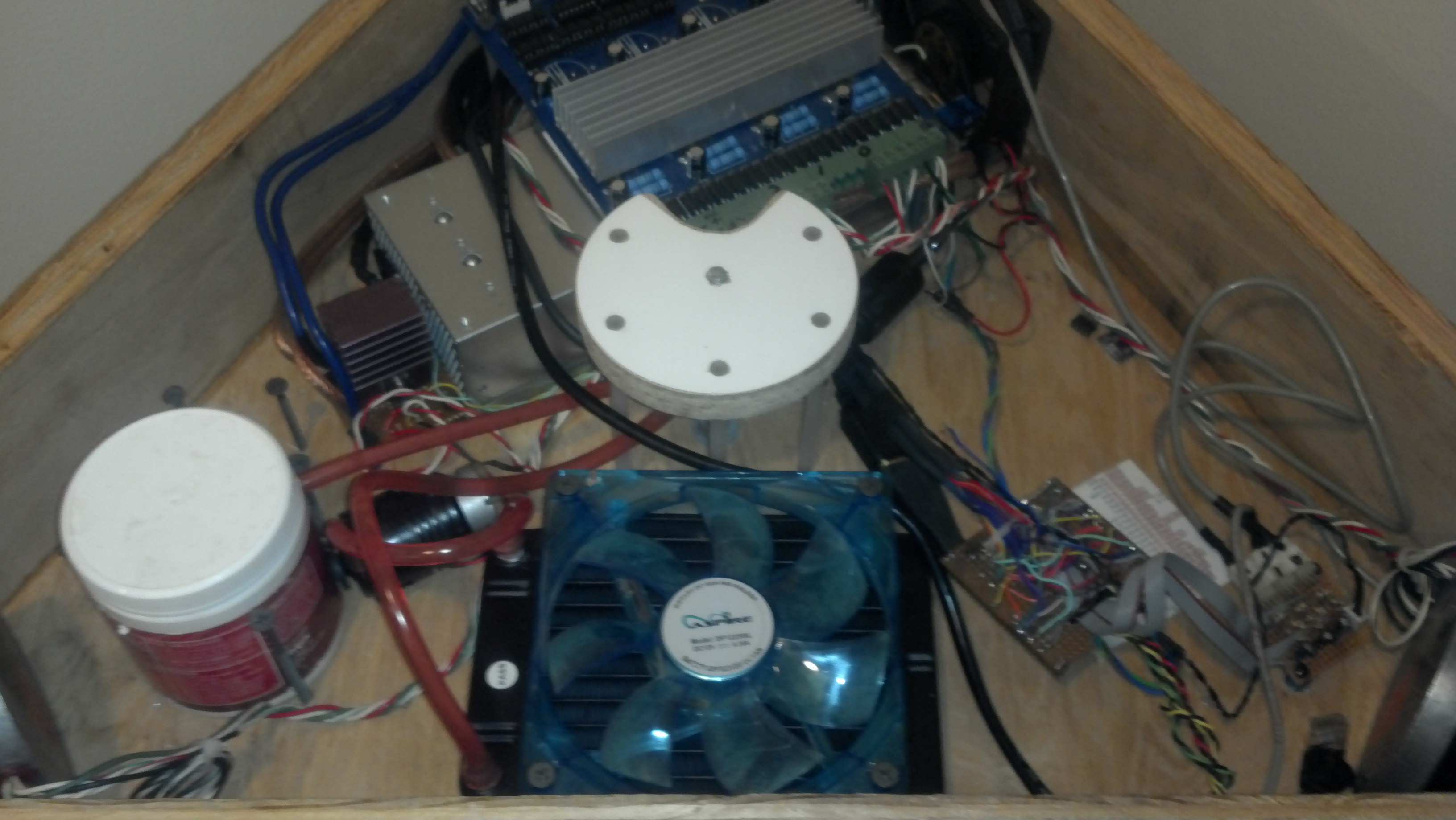
Switched to a junkyard HP server power supply giving me 75amps@12v to play with. Added some fuses. :)
![]()
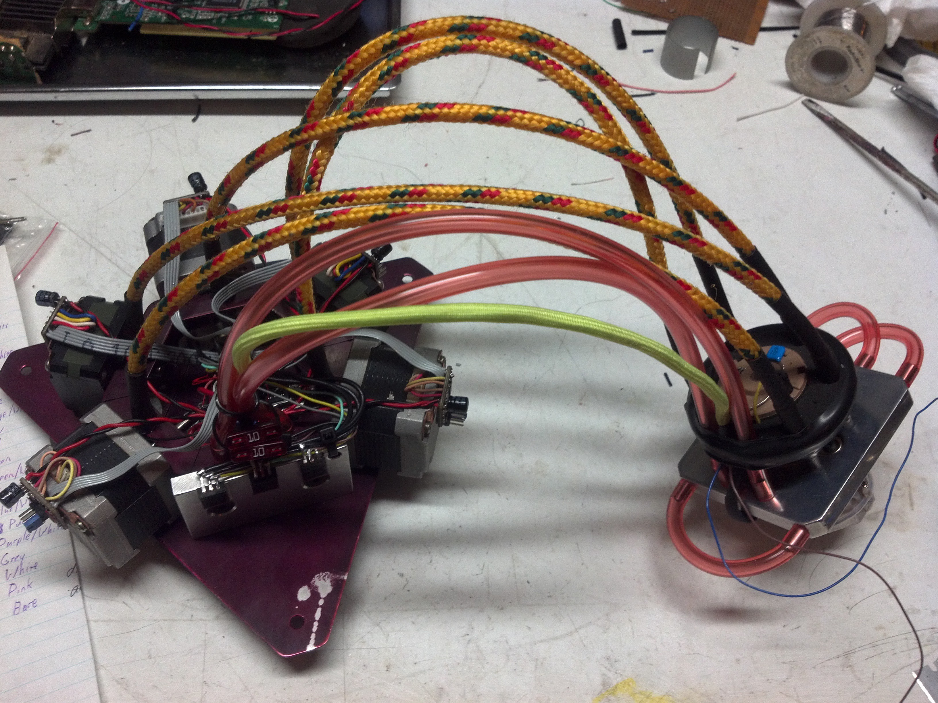
Added 4 more extruder motors for a total of 5. This gave me the choice of either having 20 feet of bowden tubes, or mounting the mass of 5 steppers to my hot-end. Neither was acceptable, so designed a floating carriage. Machined it flat, and bent it to shape.
![]()
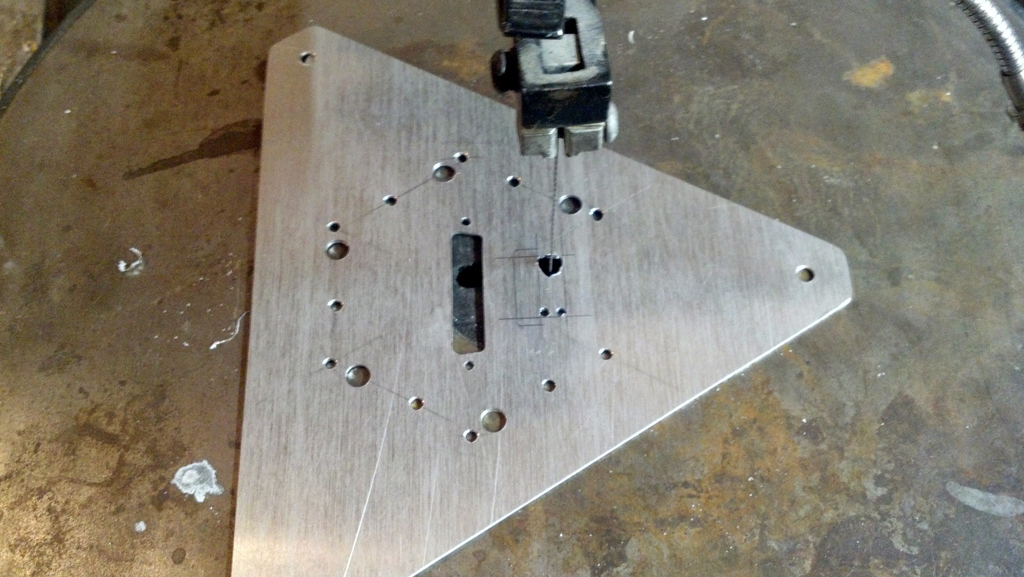
![]() 'Machined' the top plate.
'Machined' the top plate.![]()
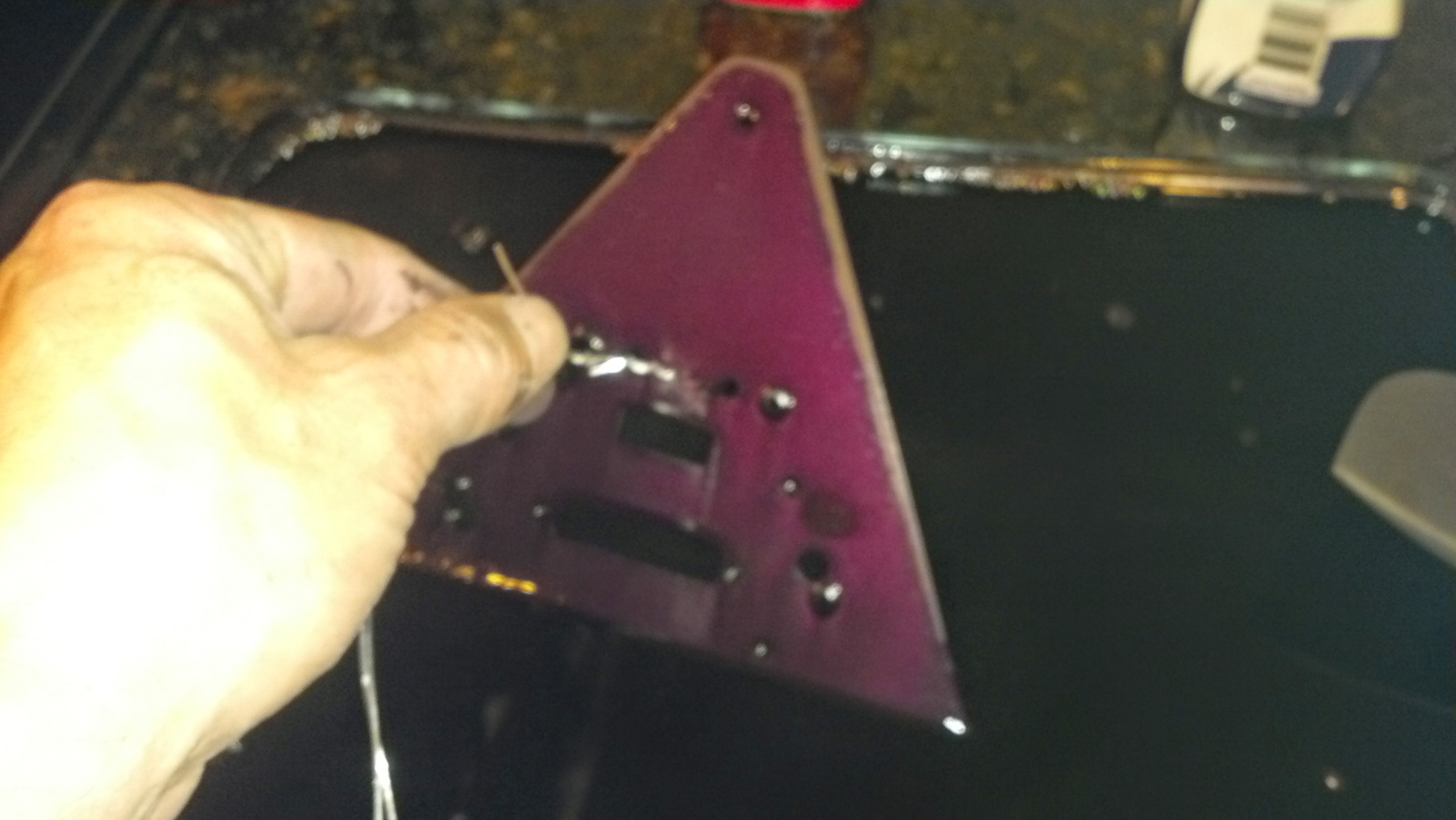
RIveted. Annodized.
![]()
Rather than run ~30 decent gauge wires to the floating carriage, I switched to using DRV8825's and mounted them to the steppers. The backplane of the DRV8825 was soldered to a bit of copper, and then mounted with the existing stepper bolts. The power mosfets were also mounted to the carriage.
![]()
Now I can just provide power, and route the signals to/from it via a PC parallel cable (with no wires to spare).
Putting that many steppers in close proximity didn't work so well. PLA would soften at the temperatures generated in the floating carriage and that added up to a bad day. So... added liquid cooling for the steppers. Note the new black tube beneath the steppers. I was already doing liquid cooling for the cold-end and mosfets at this point.
![]()
Wrote the software to support it. There was much borrowing from some of the forward thinking guys at the Machinekit project and a small amount of original code. Basically I added a scaling factor to each extruder and the mixer speed, added some g-codes (actually M codes) to match, and wrapped it in a cool UI.
To simplify things, I started with a 'Velocity Extrusion' branch so 'there is no E'. The amount of filament to extrude is calculated from the instantaneous velocity of the print head on the fly.
There is a custom branch of Slic3r which outputs the correct flavor g-code.
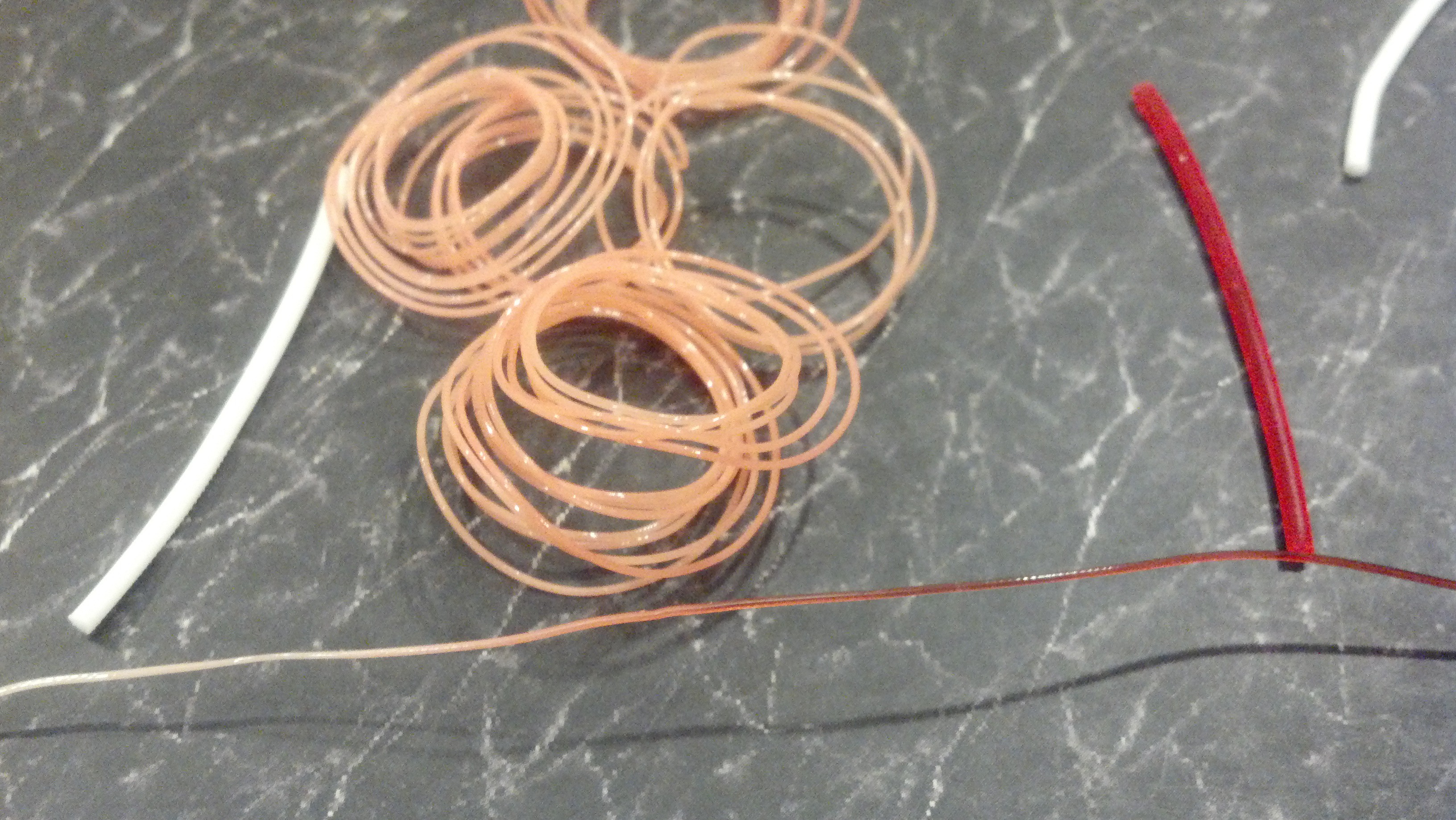
Result... Active mixing works!
Here is a pile of pink made from white/red and then a demo of how fast I could change between them.
![]()
But...
All versions of the active mixing hot-end thus far have eventually started leaking and eaten themselves. The longest running one thus far lasted about a week with light use. I've now gone through 7 revisions of this hot-end:
Versions 1-5 all had some fatal flaw and never worked well enough to actually print anything.
Version 6 printed and stayed sealed for a good long while (a week!), but it eventually leaked around the mixer shaft and ate itself. It had other issues too as it had a lot of thermal mass and suffered from a long melt area. It was modified many times until I machined away too much to continue with it.
Version 7 was born. It was 1/4 the thermal mass, smaller, easier to machine, but it also implemented a new spring loaded idea for mixer sealing which turned out to be terrible. It ate itself in 5 minutes.
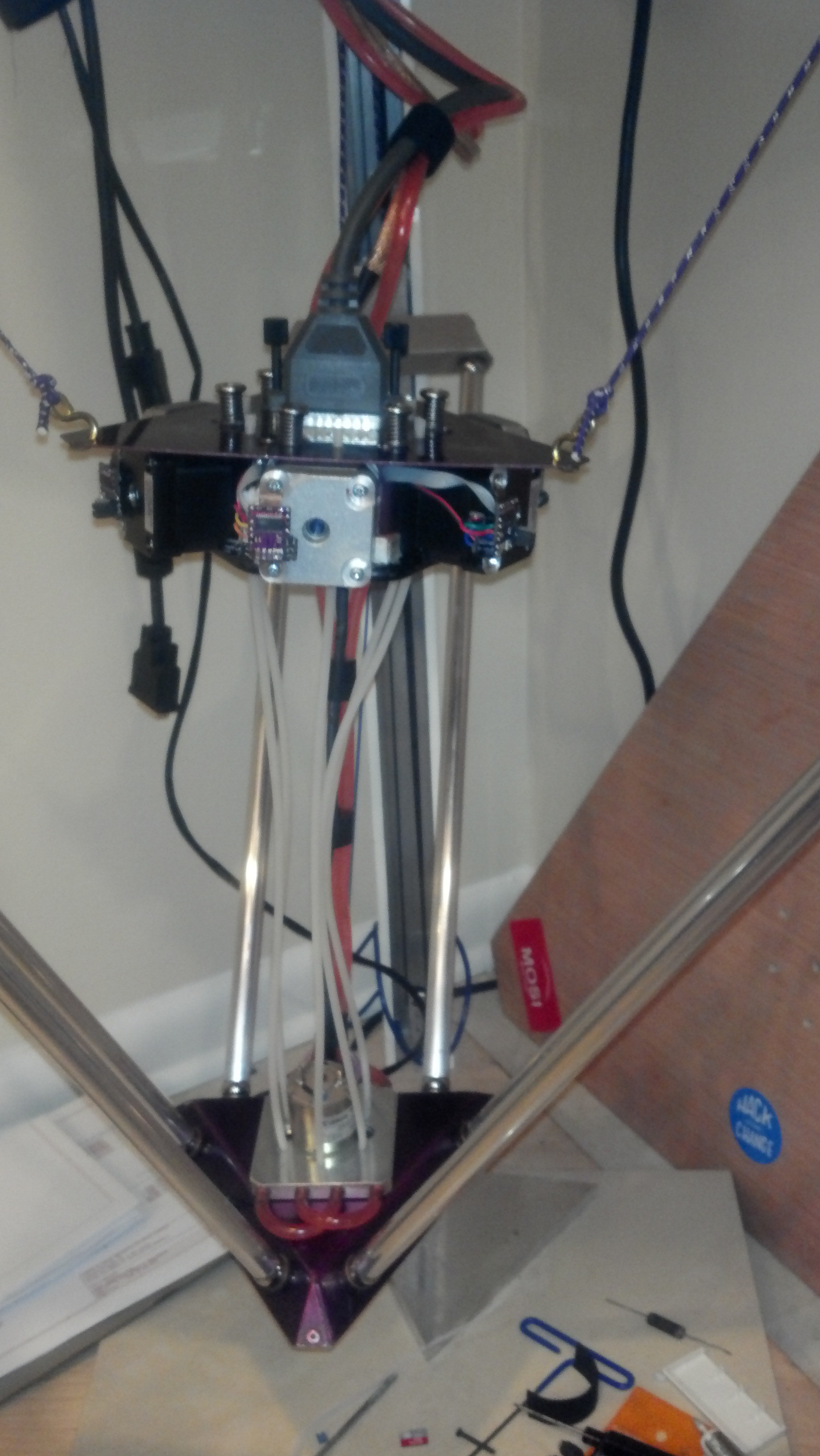
Version 7.1-ish was born. I re-machined Version 7 to use the same type of seal as Version 6 and have added the ability to adjust the seal tension after assembly.
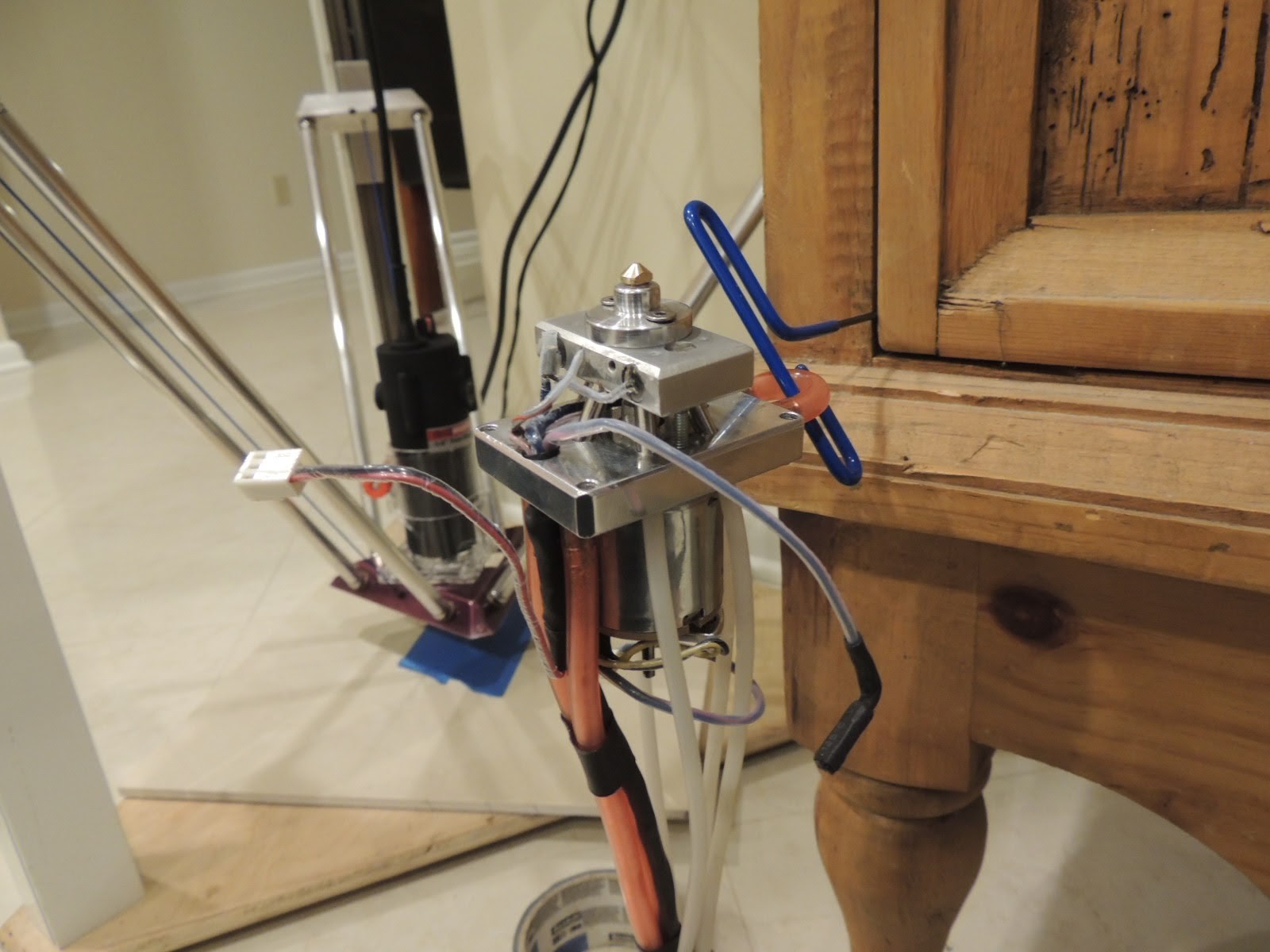
Here is the (nearly) latest revision of the hot-end. You can see a router experiment in it's place on the delta in the background.
![]()
Then.. life happened and I had to take the last few months off.
I finally was able to spend a few hours on this in the last week, but on final assembly I damaged my mixer seal before I ever got to try my new hybrid. :(
I now have some glass filled PTFE to play with though, so I'm going to see how that works when I get the time to re-make it.
-
cymk, and poor temp resolution
01/20/2015 at 19:30 • 0 commentsI did some tests of the 555 timer based temp feedback. The resolution at operating temperature was poor ~7 degrees. The resolution at room temperature was a lot worse ~30 degrees. The refresh rate was also poor. Seems the sensor chip was outputting at 1hz. That would be fine for fan speed feedback, but a little low for temperature feedback I think.
CYMK is also on hold. I'm missing 2 steppers, 4 stepper driver ICs, and most importantly I came up 2 outputs short on my parallel port interface. After extensive research about various other IO hacks, including being able to get the needed IO by bit banging the serial port and level shifting the output from Rs232 back to TTL, I decided it wasn't worth the work.
I've broken down and ordered a Beaglebone black. That will give me all the IO I will ever need, good floating point performance (as this is a delta, every move involves some floating point calculations) and no more bit banging as I have 2 dedicated 200Mhz hardware PRU's, for $45.
From the spec sheet and browsing around, I've determined I should run it off the ATX standby line, and enable the ATX power after it is powered via a GPIO. This eliminates the issue I was *going* to have where if I just powered it all off the ATX and tied power-on, my sensors/parallel port card would have driven GPIO pins before the processor was ready for it, and would have destroyed it.
Now where is that HDMI to DVI cable...
-
Temp feedback and start of cymk
01/16/2015 at 23:11 • 0 commentsFinished the code for reading the mobo fan speed sensors and importing that into Machinekit as feedback for my thermistor. Roughly calibrated it.
Change the range of the 555 down to 60rpm at room temp as I maxed out the frequency readable by the fan speed sensors at 300c. What's worse is when that happened, it seemed to wrap around... which would have led to a nice smoking hot end as I'm feeding it 80w instead of the normal 30w.
The hotend overkill is in support of plans for a larger cymk capable extruder. Designed an active mixing head with low mixing volume for fast color changes. Missing some parts, but it's coming along.
Arcus-3D-M1 - Full Color Filament Printer
Active mixing, fused filament fabrication 3D printer.
 'Machined' the top plate.