Thought I'd have it all done by now, but everything takes longer than you think it will! Let's pause along the way and look at a few design details that might be innovations - maybe even useful innovations!
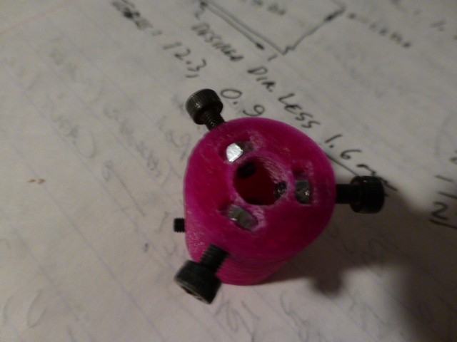
The first innovation is in the coupler that will join the drive motor to the 8mm threaded rod that propels the plunger. The end that hooks to the 8mm rod is pretty standard: just three 3mm nuts pocketed into the plastic so screws can be tightened against the rod. Clean out the pockets, drill out the bolt holes and press in the nuts. Done.
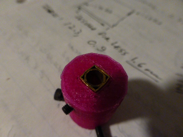
The end that hooks to the motor shaft is perhaps more interesting. I haven't seen this approach used. I cut a length of 6mm round brass tube (5mm id to fit the motor shaft) and coaxed it into a similar length of 1/4" square brass tube. The round tube fits snugly into the square tube. Slight distortion results when the round is pressed into the square, but it's minor. The square tube fits (press fit) into the coupler body and a 3mm clearance hole is drilled through the tubing and threaded. A set screw can now be tightened against the flat on the motor shaft. This provides a very secure, non-slip connection to the motor.
Next, we'll look at the method of anchoring the delivery hose to the discharge nozzle. What's need is a compact way to secure a plastic hose. Stay tuned.
 doctek

Discussions
Become a Hackaday.io Member
Create an account to leave a comment. Already have an account? Log In.