To make the experience fit your profile, pick a username and tell us what interests you.
We found and based on your interests.

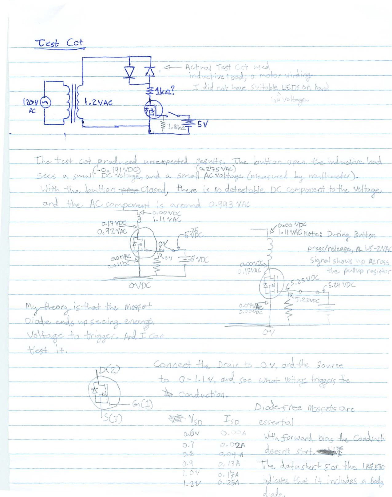
I planned to use LED's to check that the N-channel MOSFET (IRF530N) was actually conducting in both current directions when a 5V signal was applied to it, but I did not actually have any LED's on hand that would turn on with less than 1.5V, so I substituted a large coil as the load with a suspended magnet to detect the passage of AC through the MOSFET.
Unfortunately, there is leakage with 1.2 VAC applied to a MOSFET. The body diode begins to conduct at and below -0.7VDC, which I assume is similar to its action under AC cycling. The amount of current conducted was quite small, but did produce a detectable vibration in the suspended magnet, which is not acceptable for my planned application.
Fortunately, I can move forward with testing the concept of 3 phase electrical commutation at low voltage, high current with this small amount of leakage. I will eventually need to drop the voltage down to or just above 0.6 volts for the next version (which means using more MOSFETs paralleled to reduce the Rds(on) of the MOSFET at the lower Drain-Source voltage, which may become nonviable at such low voltages due to the cost).
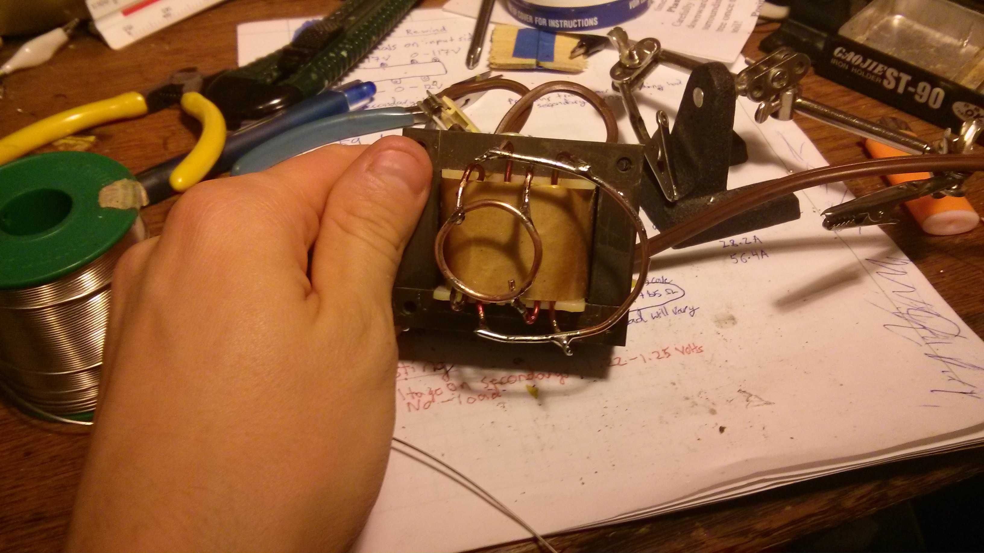
De-enameling the leads took too long, scrapping it off with an exacto knife.
Soldering everything together was pretty quick.

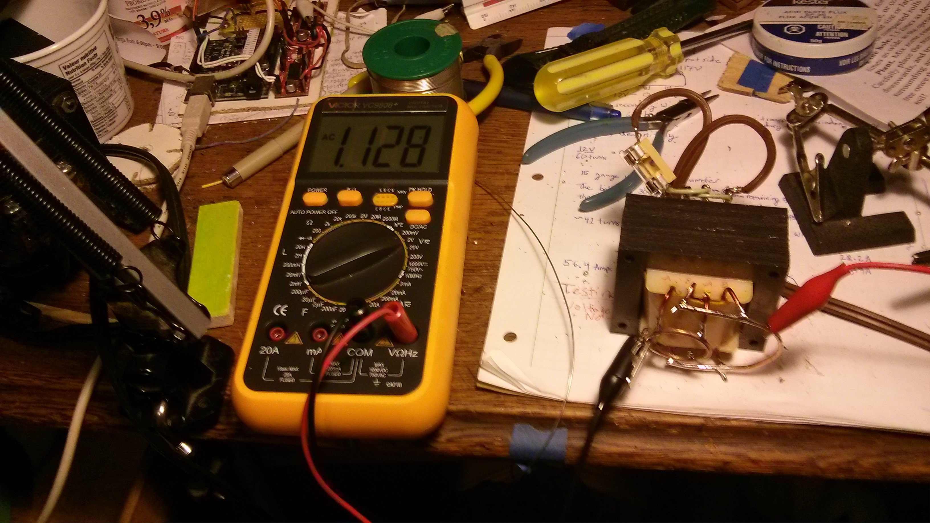
Oddly once everything was connected the voltage output dropped a bunch, by almost a tenth of a volt.
Still need to figure out a variable load for testing, and then a MOSFET bank that can switch such low voltages without wasting all the power on the way to the load.

Create an account to leave a comment. Already have an account? Log In.
Become a member to follow this project and never miss any updates
What you're seeing as 1.2v between windings is just capacitive coupling. If you load it with any real sort of load it will immediately disappear.
It's an artifact of having a meter with an extremely sensitive input module (10Mohm)
As for joining your windings to a main output bus, make sure you make the connection in a mechanically secure way before soldering them. Depending on solder to make your connection will result in disappointments as solder has a much lower conductivity than copper. At those currents, and with that little overhead voltage every millivolt of voltage drop matters.