The first version of this project was intended to be cheap, fast, and use the bare minimum number of components. I have a bunch of those boards now, so I'm good on that front.
A good way to up my game on the reliability stand-point is to take lessons from the Arduino itself. I checked out the schematic before, but was mainly looking for cool features or maximising compatibility. It's time to revisit that a bit.
Starting from here:
https://www.arduino.cc/en/uploads/Main/Arduino_Uno_Rev3-schematic.pdf
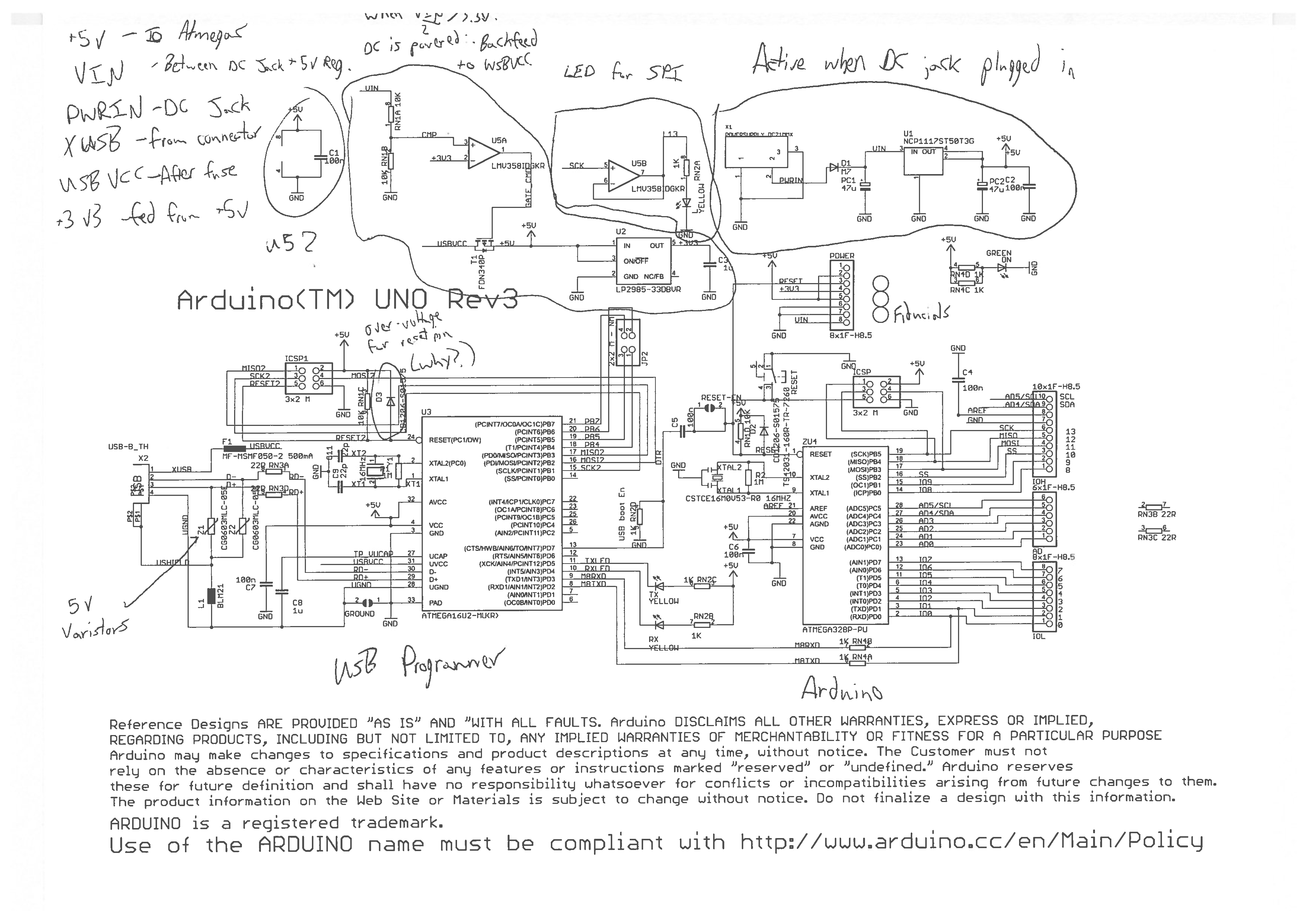
This is a pretty bad schematic!
Here is a quick and not-complete analysis of it. It's not The Worst Schematic In The World or anything, but it could be way better.

The first, most obvious thing is readability. For an open source project that is designed to ease people into hardware, just shitting the components all over the page like that is a big "fuck you".
- +5v
- VIN
- PWRIN
- XUSB
- USBVCC
- +3v3
VIN is only active when the DC jack (PWRIN) is on. So what that circuit does is backfeed the 5v rail into the USB power rail when the DC jack is being used.
Those are my big complaints, I guess.
.
The protection circuitry for the USB side is getting used in my design for sure, I am not an expert on that bit. Probably not going to include the DC jack or power components, does anybody use those?
Edit: When only USB is plugged in, the entire board is getting powered through the reverse polarity protection of the P-FET. WTF.
 Jarrett
Discussions
Become a Hackaday.io Member
Create an account to leave a comment. Already have an account? Log In.
I helped run a classroom exercise awhile back where we recreated the Leonardo from schematics. The schematic documentation could definitely use some work, particularly the net names and functional blocks. I also couldn't easily find machine-editable schematics, like a KiCad *.sch file; just *.pdfs. Ah well. I suppose it's an open source project, so I should do it and submit a PR.
Are you sure? yes | no
You miss a point here: It started as a open source project, but no-one in the beginning cared about the schematic or why it works. They gave you a board, a maximum-reduced "IDE" and off you go. Got your first program working in seconds. Even if there are quirks in the schematic even now. those boards work like a charm. They do exactly what they are built to do.
It's really the same about all the "anti" articles and stuff... And it's not even you are forced to use this or that layout. You can choose from dozens of boards.
The barrier to start programming with PIC, ARM etc. is much higher, even today. Arduino has its definite downsides but come on, it isn't that popular because it's shit and doesn't work!
Are you sure? yes | no
I did choose to use another board :)
This schematic has nothing to do with how it was in the beginning - It would take a day or two to make a cleaner schematic that would be easy to read and good for teaching people the hardware itself.
Speaking as a professional, if one of my underlings came to me with this schematic, I'd make them redo it.
That's really the whole point of this log. I'm not speaking to Arduino as an ecosystem, or comparing it to any other kind of microcontroller, just talking about this schematic out on its own.
Are you sure? yes | no