The Toast-R-Reflow design consists of a power board and a controller. When I started the project, I didn't actually have a reflow oven, so the power board was designed with through-hole parts. This has worked out fairly well. There aren't very many pieces to the power board, and there's little incentive to minimize its size.
Each channel of the power switcher is a basic opto-isolated triac circuit consisting of a MOC-3020 opto-isolated driver triac and a BTA-20 power triac.
In designing the power board, the biggest limitation was thermal constraints. I got the largest heat sinks that I could reasonably fit into the allotted space, but the thermal calculations must be quite conservative, since we're building it into an oven. Fortunately, the space behind the controls in the oven I selected (and this is likely true for most) stays relatively cool during operation. This is largely because the area is liberally ventilated, likely in an effort to insure that the user controls remain cool enough to be handled regardless of how hot the oven interior might get. Nevertheless, the operating specification for the power board is an ambient temperature of 50°C. Given the heat sink has a cooling capacity of 5°C per watt and the BTA-20's maximum operating temperature, its own junction-to-tab thermal resistance and the device power dissipation curve, what that winds up with is a maximum current rating of 8 amps. Since I'm in North America, the toaster ovens I use are 120 volts, so that 8 amps yields 960 watts. That's not quite enough, so I designed the power board with two channels. Since most toaster ovens have an even number of heating elements (either two or four - divided between the top and bottom) and they're usually controlled separately (so that the oven can support broiling), this works out just fine. The two channels can handle 16 amps total, which would probably be enough to start tripping circuit breakers if it were all used.
The input side of the MOC-3020s, like all opto-isolators, is merely an LED. Light the LED and the relevant heating element will turn on. But it's all-or-nothing: once a triac is turned on, it will stay on until the next AC zero-crossing. To get fractional power, you either need to do what a lot of lamp dimmers do and delay the triac turn-on during each cycle, or you need to do what every microwave oven does and just turn the elements on and off repeatedly to establish a fractional duty cycle. To do the former in software, you'd need to establish a zero-cross notification for the controller so that it could time the turn-on of the elements at least. To do it in hardware would require some sort of D/A conversion. The latter option is far, far simpler. As long as the time period for the PWM system is substantially longer than the AC cycle time, you can ignore the zero-crossings (in theory, it's still better to turn the triac on at zero volts, but in practice this has not proven to be necessary in my experience). I chose 1 second as the PWM interval. For 50% power, you turn the elements on for 500 msec and off for another 500.
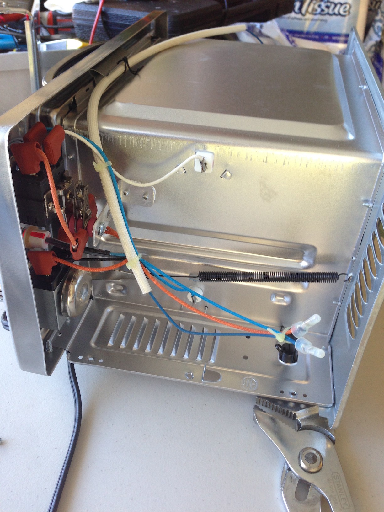
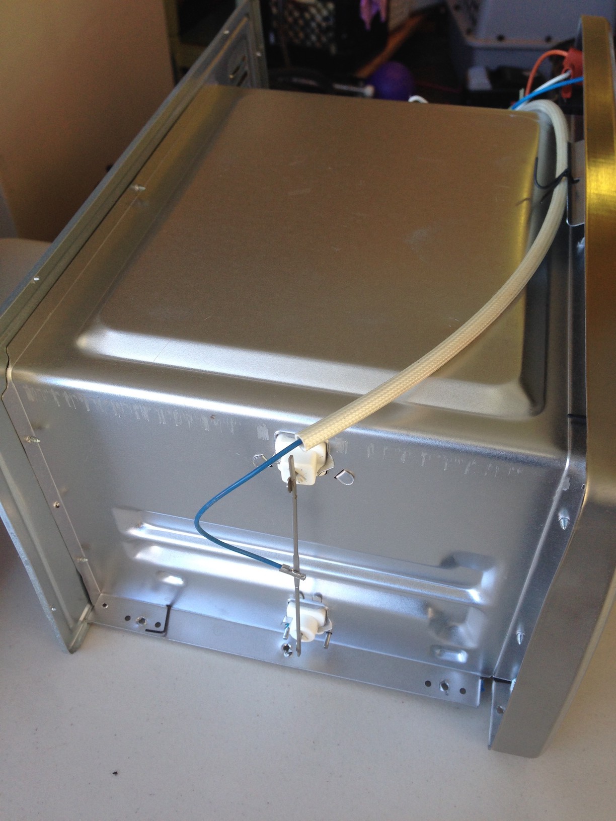
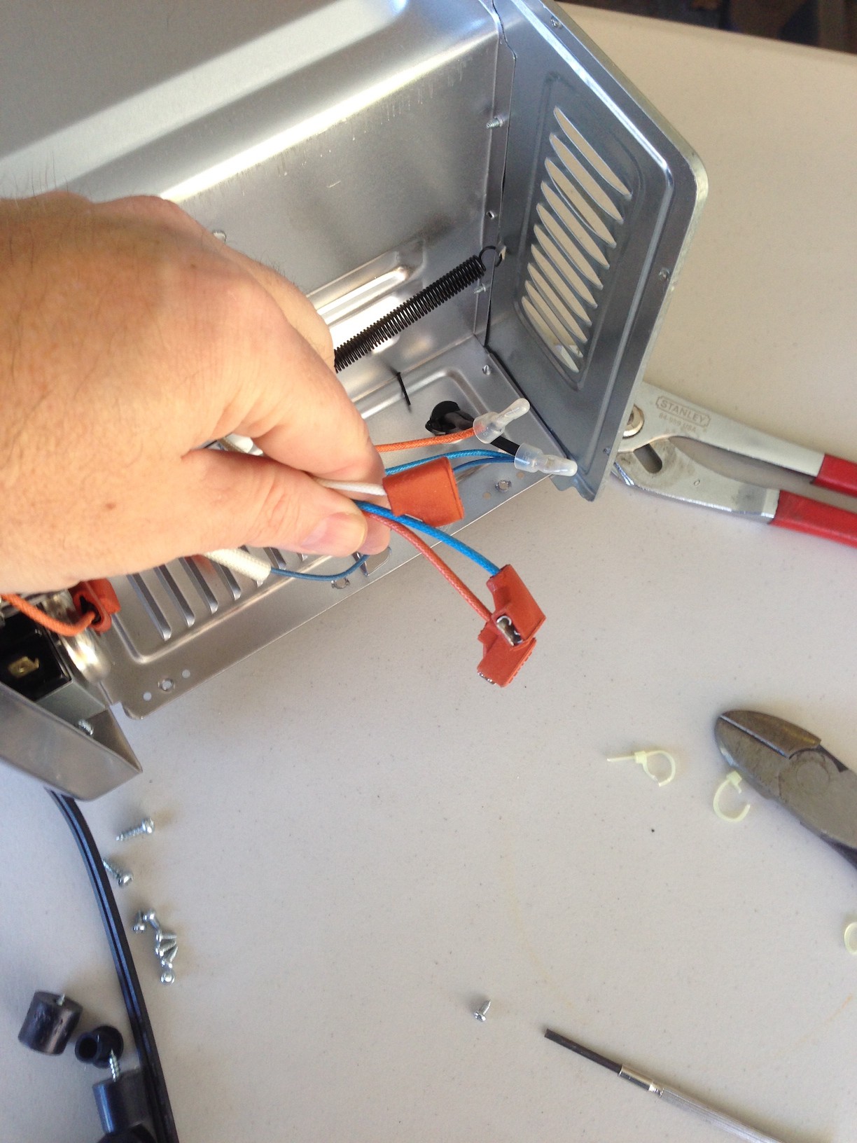
The power board has three board-mounted QD terminals. The oven I chose (and I expect quite a few of them do as well) used QD terminals for all of the chassis wiring. There were three of particular interest - one from the hot line of the incoming wire from the AC plug, and one from each of the top and bottom elements (in my case, the AC hot line QD terminal was the wrong size and needed to be replaced. I just used an ordinary crimp terminal from Home Depot). The three interesting QD terminals were attached to the matching terminals on the power board and the board was secured to the outer chassis with #4 bolts and 1/4" standoffs. When selecting a mounting location, make sure that nothing can come in contact with the board or wiring. Be particularly cautious mounting the board near ventilation holes - you don't want to be able to poke anything through the hole and touch the HV traces...
Read more » Nick Sayer


Do you sell kits online?