 williamg42
Design Specification
Sensors
- The board will host multiple MEMS IMU on different buses, for redundancy and to allow the implementation of a multiple sensor Bayesian filter.
- The board will host a single GNSS reciever to allow localization accuracy of +-2.5m when outdoors. GNSS was picked for access to both US GPS and Russian GLONASS systems, and a quicker cold start time.
- The board will support an analog front end capable of measuring voltages up to 20V for battery voltage monitor.
- The board will support an analog front end capable of scaling a -5V to 5V signal to 0 to 1.8V.
Communication
- The board will host a XBee Pro module
Actuation
- The board will support direct PWM outputs for control of external devices.
- The board shall not provide power for these external devices.
Part Selection
IMUs (Version 1)
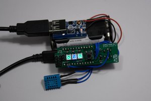
BNO055 was selected for two of the IMUs, mainly due to its use in Pixhawk controllers. LSM9DS1 was selected as the third sensor, for redundancy, a different I2C address, and because it looked interesting.
Version 1 is the currently completed PCB show in the photos above. Version 4 is the next version of the board that is currently under work.
Sensors (Version 4)
BNO055 leaves some things to be desired, and electrical noise from the rest of the system causes noise on the magnetometer, so the BNO080 will be used instead. It is approximately 3x more accurate, due to the superior fusion algorithm used onboard. It also provides an estimate of how accurate the data it provides is, which is important for the gps/imu filter I am working on. It also support an external barometric pressure sensor.
| 5.2mm x 3.8mm x 1.1mm |
| Up to 1KHz |
| 2.0msec |
| 3.0° - Dynamic 1.0° - Static |
| 0.5°/min |
| ± 2000°/sec |
BHI160 will also be used as the second IMU, and the sensors are comparable in accuracy to the BNO080, the resulting sensor fusion is not as good. However, this IMU does support an external I2C magnetometer sensor, which I will design a carrier board for and remote away from sources of electrical noise. This will allow me to accurately determine magnetic north.
BMM150 is the external magnetometer, which is supported as a direct input into the fusion algorithm in the BHI160. It actually quite nice as sensor go, although it is a bga, which will be fun to reflow.
Logic Level Conversion
The XU4 IO voltage is 1.8V, and thus logic level conversion is needed. The TXB0108-PW was selected due to OEM recommendation.
GNSS
A5100-A was selected from Maestro Wireless Solutions since it is a GNSS capable receiver, with active antenna support. It is an all in one module with minimal external components.
Schematics (Version 4)
Magnetometer carrier board

Sensor Board top level schematic, with odroid xu4 connections, logic conversion, on-off button, and i2c to differential i2c conversion and RJ45 connector.

Sensors

Power

Analog front end, converts a 8V to 13.8V and -5V to 5V signal to 0V to 1.8V to be fed into the odroid xu4.

I2C controlled LED driver (outputs programmable PWM signals, 16 channels)

Xbee Serial communication link

Board Layout (Version 4)
4 layer board with a segmented 3.3V 1.8V power plane and a GND power plane.


 Tom Meehan
 Nolan Moore
 Ruediger F. Loeckenhoff