 Carl Bugeja
So torque is the biggest weakness of my tiny PCB motor. This was measured it to be 0.9gcm.
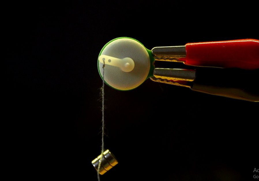
But it is something that can be improved. These are three ways how I tried to improve it:
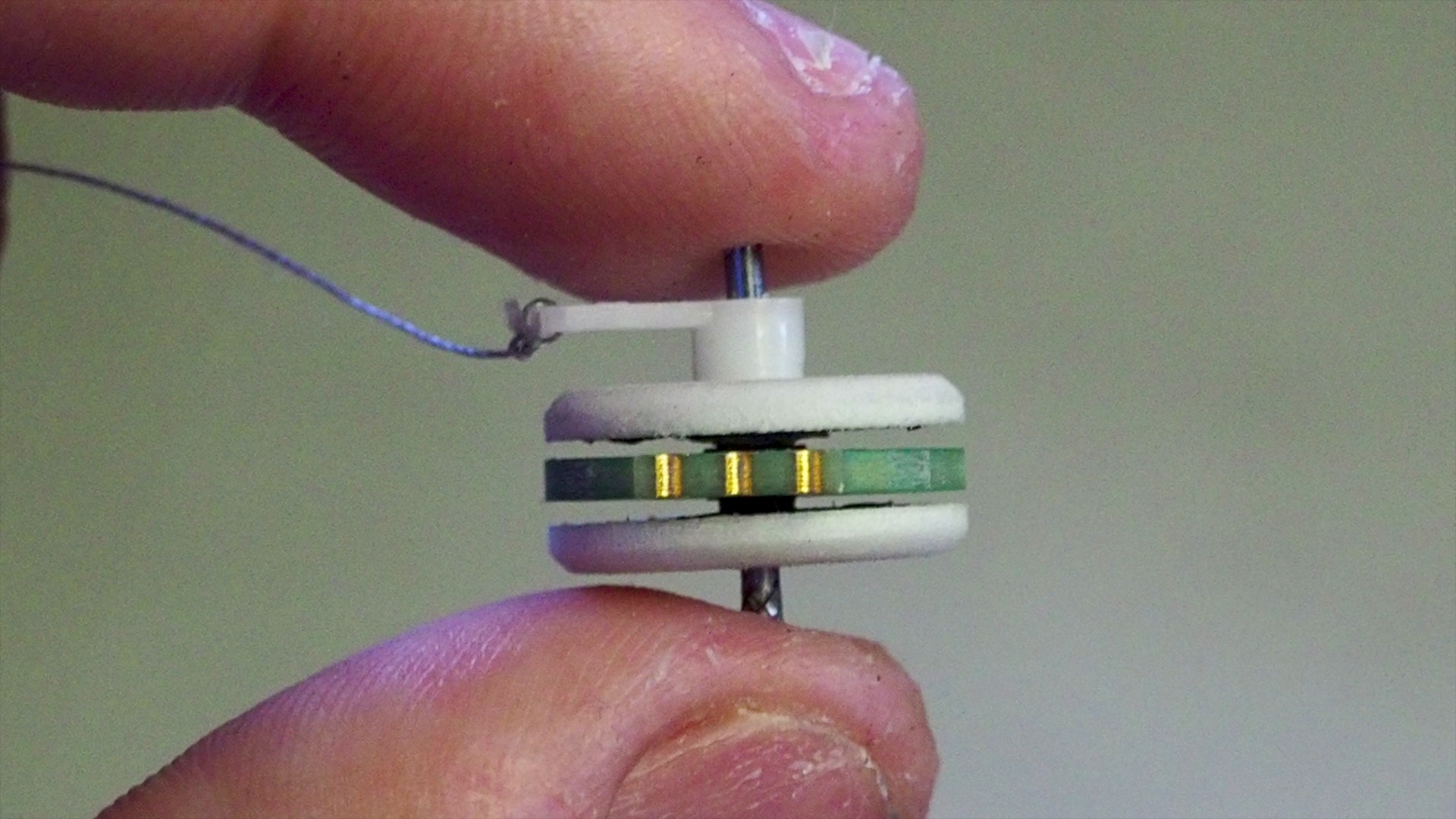
- Double Rotor - Some people in the comments suggested to try and use a double rotor. This will increase the magnetic field produced by the neodymium magnets and therefore will also increase the motor's torque. But in practice this was not the case and it barely had any effect. The measured torque was 0.9gcm (the same as with one rotor).
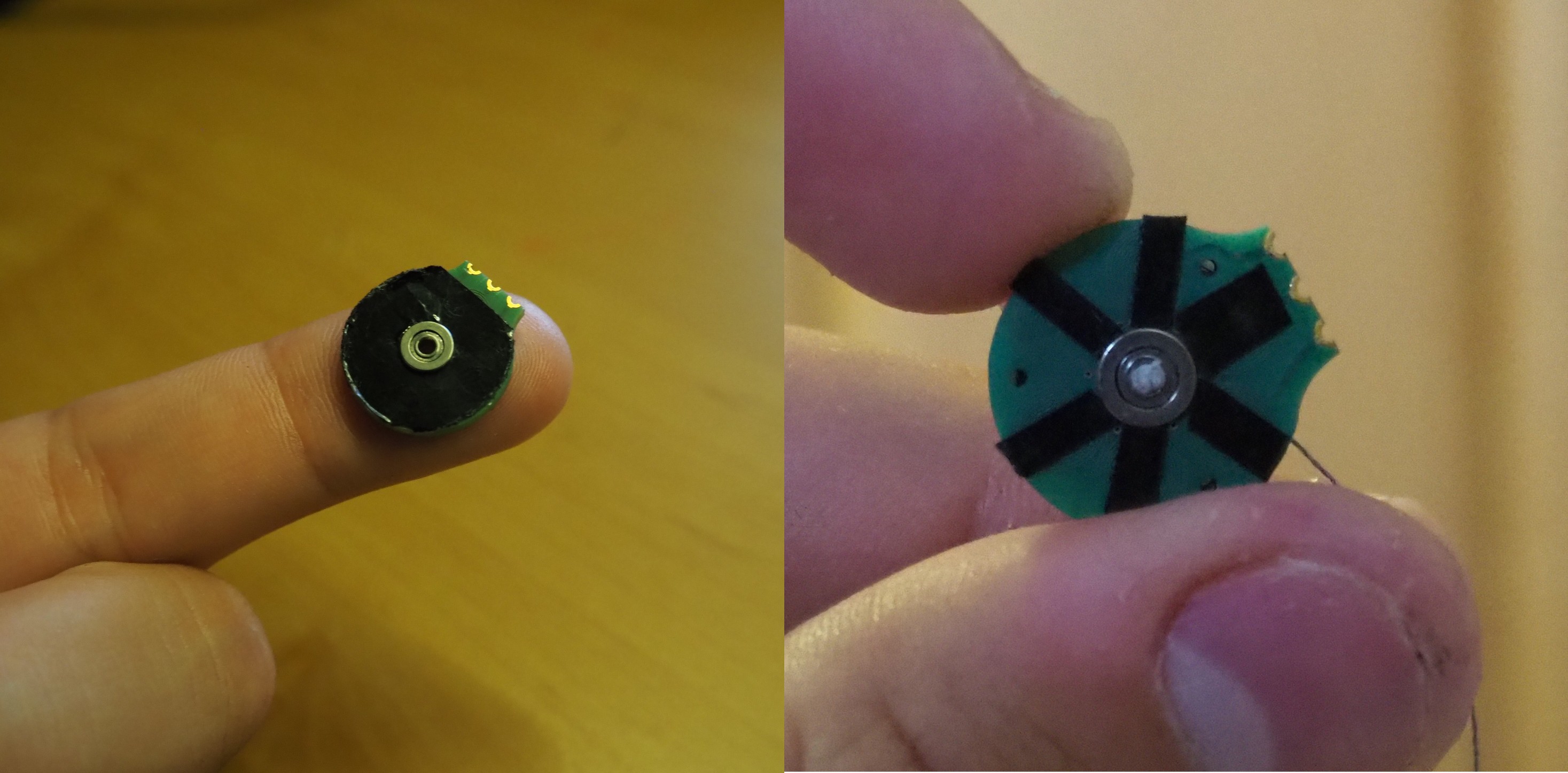
- Ferrite Sheet - This was used to act as a reflector for the magnetic field and increase its strength. Two different shaped cores were tested. The uncut one gave a higher torque value and has increased it from 0.9gcm to 1.5gcm. The only down side of this is that It has also increased the pcb's temperature from 70°C to 90°C due to eddy current losses.
- Delta configuration - Other simple way to increase the torque is by changing the configuration to a delta winding. This way the coils will be powered with a higher voltage, so it will also increases the torque and temperature (hopefully not by much). This approach was not tested yet.
Check out the full tested video:
Discussions
Become a Hackaday.io Member
Create an account to leave a comment. Already have an account? Log In.
Why not stack the PCBs? e.g. PCB, rotor, PCB, rotor, etc...
On the stacked rotors, doesn't the magnetic field from one side interfere with the field on the other side? e.g. you have to separate the stacks and provide each rotor with it's own PCB windings. Perhaps as much as 10 or 20 mm.
Are you sure? yes | no