 Carl Bugeja
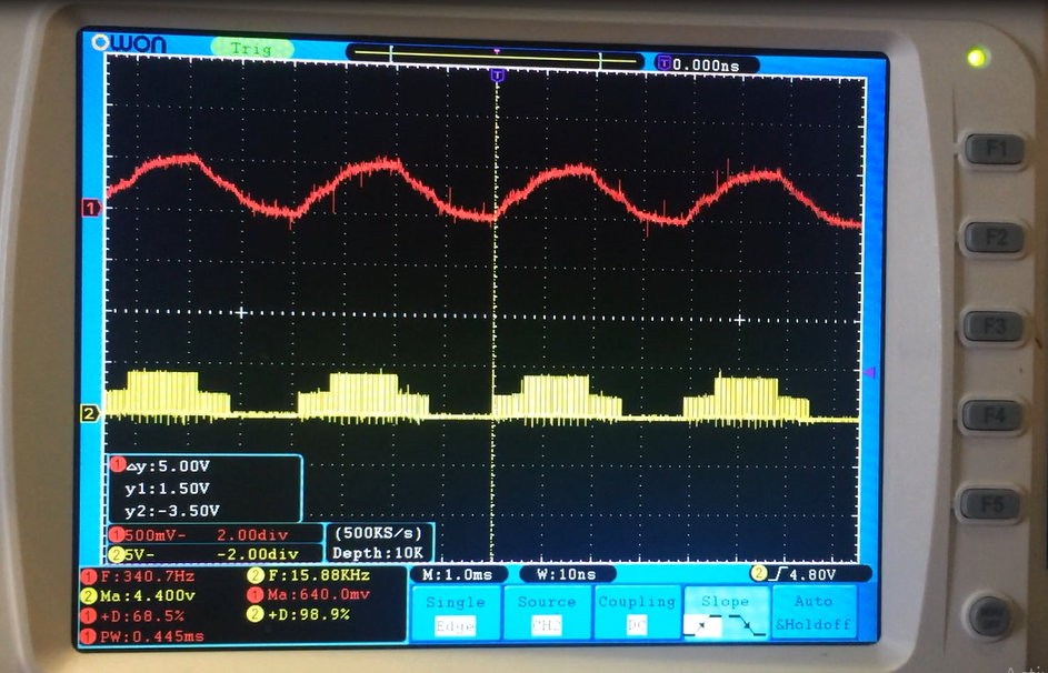
My plan for speed controlling the PCB Motor was to implement a sensorless back-emf speed controller, which works just like every other brushless ESC. It measures the time it takes to detect the zero-crossing point from the under-driven phase, and adjust the commutation waveforms according. However, during testing the back-emf generated in the windings of the PCB motor was a little weak.
Plan-B is to use a hall sensor to implement the closed loop speed controller. This will be a little more pricey but will also include positional sensing.
Discussions
Become a Hackaday.io Member
Create an account to leave a comment. Already have an account? Log In.