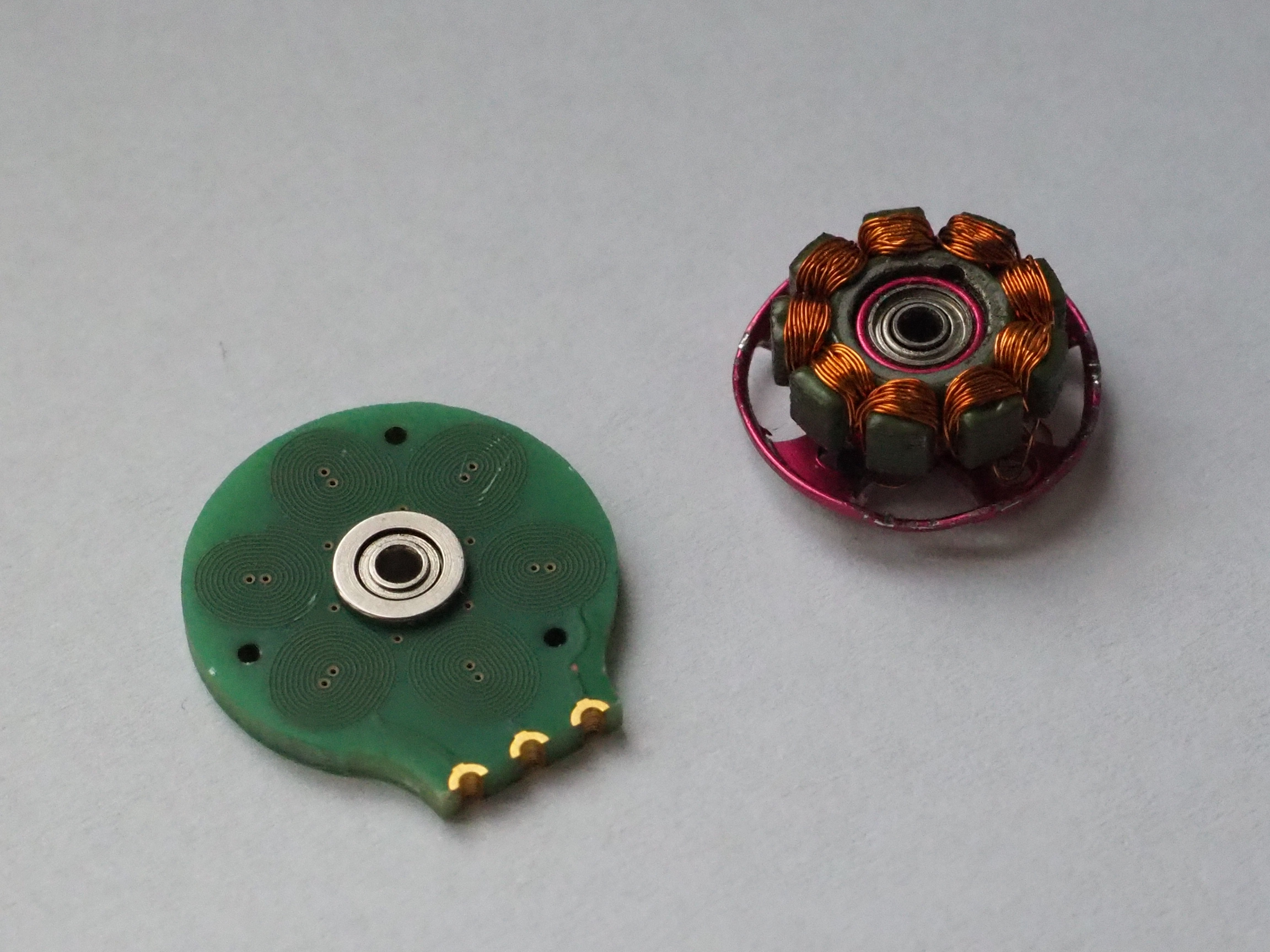
This project started with me trying to design a small cheap drone. Dc brushed motors are typically used for micro-drone designs since they are much cheaper than brushless motors. But these motors were not compact enough for my application. So I started looking into ways to make a custom brushless motors which is smaller, cheaper and easier to manufacture.
A normal outrunner brushless motor is made from a stator, a rotor and a shaft that connects the two via a bearing. Its stator has windings around an iron core to rotate the magnets on the rotor. The high magnetic permeability of the iron core creates a strong magnetic field around each coil, which improves the motor's torque strength.
I had this idea of making the stator embeeded in the PCB itself. My only concern was that to make it small, it had to be core-less. I decided to try it out and see if it had enough strength to rotate a small propeller (spoilers - it did).

I wanted the first prototype to have the best possible chance of working, while still being as small as possible. So I set the trace spacing and thickness to 0.1mm and the via's drill size to 0.15mm. Although these parameters would increase the manufacturing costs of the PCB, it was the safest starting point for my PCB motor design.
I decided to make my motor have a 4-layer 6-pole stator, to have as many windings as possible. The star type stator configuration was used to limit the phase voltage, hence limiting the overall power of the motor (more power = more heating in stator coils).

There is alot more of experimentation and testing that I need to do before trying to integrate it with a drone. I want to find the best "turns-to-size" ratio and how does that effect the motor's torque. I would also like to test the delta configuration and a PCB-motor with a 9-pole stator.
 Carl Bugeja
Discussions
Become a Hackaday.io Member
Create an account to leave a comment. Already have an account? Log In.
Have you looked at CORE Innovation's PCB stator design? Have you looked at other ways to design the PCB stator? I have thought about using Metglas material as the core and copper or silver traces on Aluminum Nitride as the PCB for an ultra high efficiency motor/generator. I'm thinking about writing a patent. Do you know what patents are out there today? The way I design the PCB isn't the way you have designed yours. We can discuss my design details if you want.
Are you sure? yes | no