-
MCP1603 Fail.
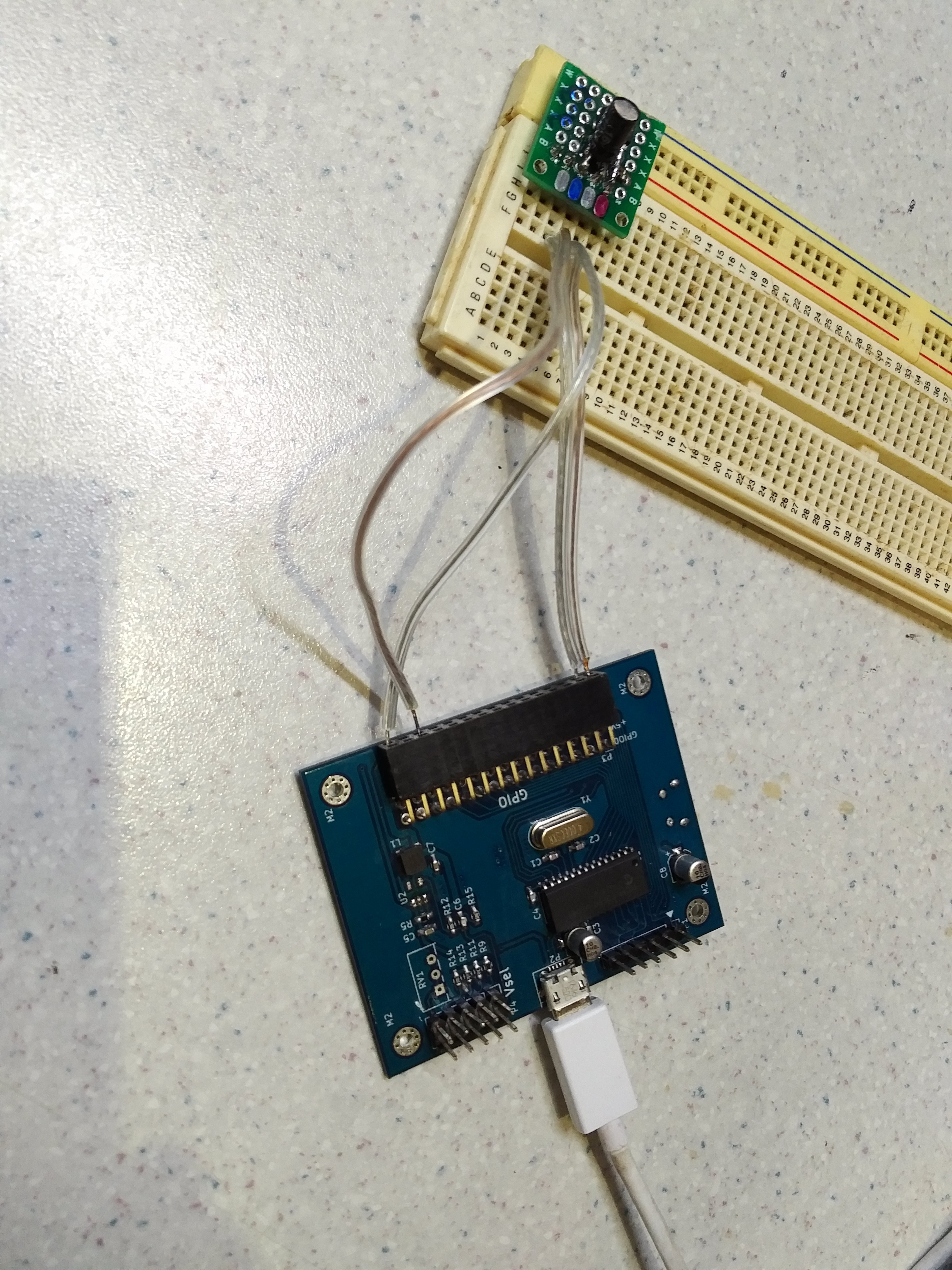
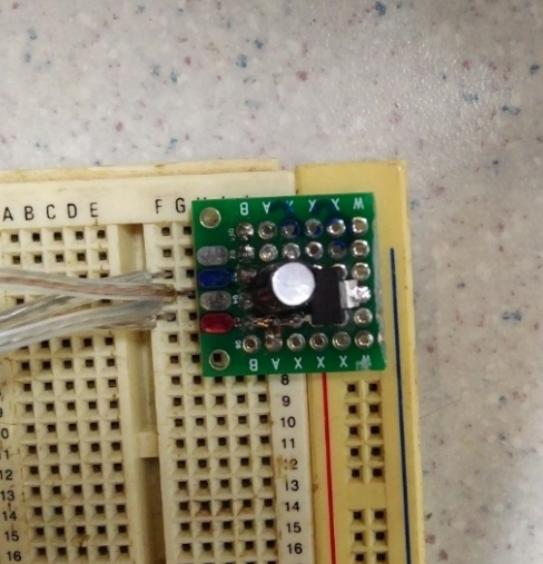
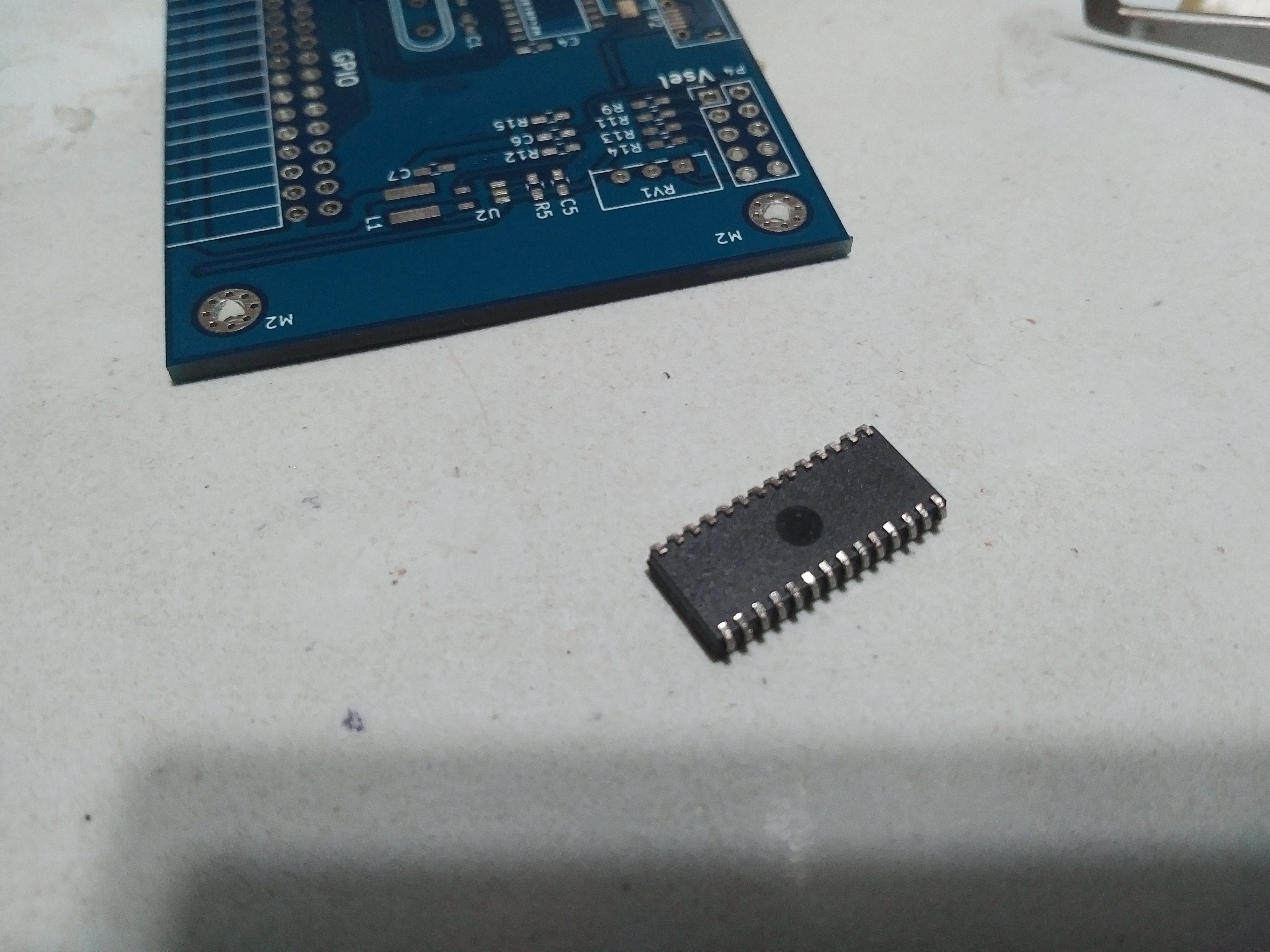
12/07/2017 at 22:57 • 0 commentsWell all the four MCP1603 ADJI that I have are dead, I don't know why, all of it release its magic smoke, maybe it does not support change of bottom resistor on the feedback voltage divisor on the fly or maybe I was wrong with something, so suspecting of my voltage level logic converter circuit (based on this) I recycled a 3.3v LDO voltage regulator, desoldered the last failed MCP1603 from the board and performed tests and the five bi direccional logic level converters worked as expected!!!.
I raised a ticket on microchip about this, I want to know what happened here, if was my fault then why the LDO is not getting hot while I use it? time will tell.
The next image show the AccessB without the MCP1603 connected to the LDO
![]()
![]()
-
Return
12/01/2017 at 23:09 • 0 commentsAfter a year of waiting I added some new things to AccessB design:
- Changed the USB port from mini to micro
- Added another micro USB port only for powering the board, this if I want to connect a cellphone to the AccessB and a wall charger.
- Added an extra pin to ICSP port to match the six pin of the PicKit 3
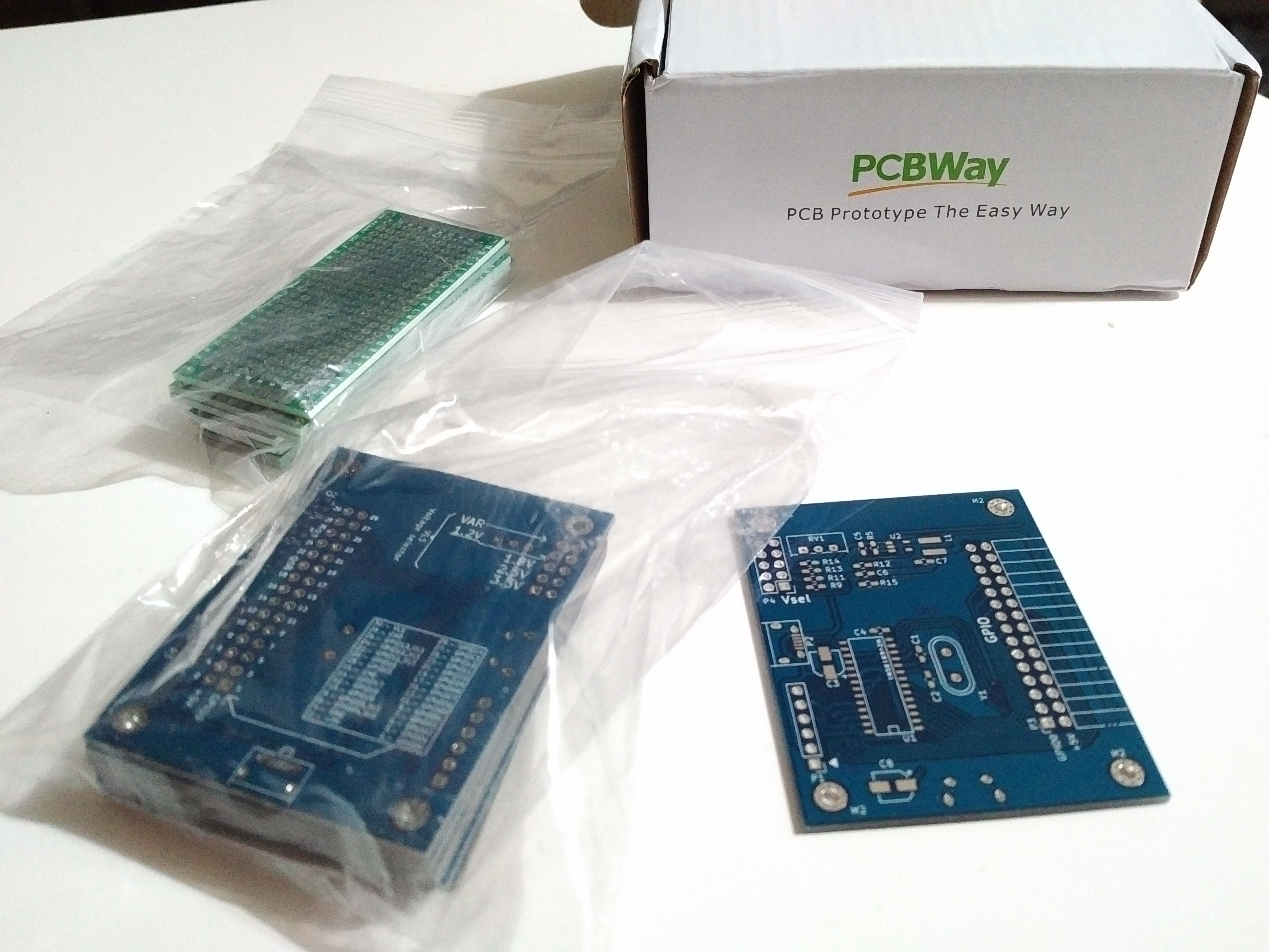
I sent the KiCAD gerber files to PCBWAY and I received this:
![]()
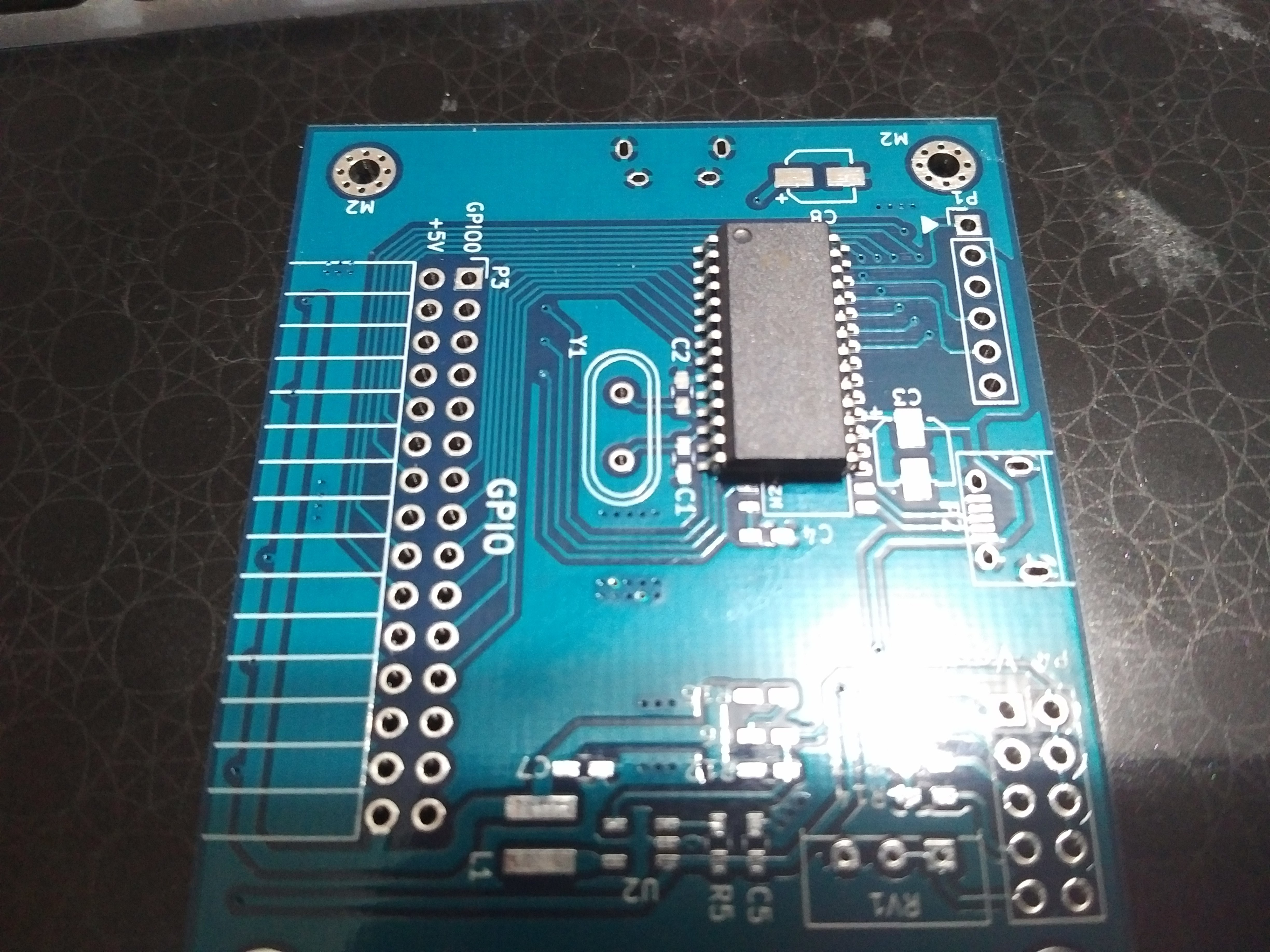
With the boards on my hands I see one mistake: the footprint for the PIC18F2550 was the wrong size, the PIC uses SOIC28 footprint same as the I used on the design so what's wrong??? look at this:
![]()
The PIC uses the Wider version of SOIC28 and I used the Narrow version (I forgot to print the PCB design and check if all parts fit ok) , the solution was easy: convert the SOIC28 Wide to SOIC-SOJ28 and all the PIC pins fit the footprints pads, with C3 too close but not a problem:
![]()
The next step was solder and test the power supply for the voltage level selection part of the voltage level shifter, it output 0.8/1.2/1.8/2.5/3.3 volts without problems, the only down was that MCP1603 ADJI don't support the changue on the fly of the bottom voltage divisor to changue the output, If you do it magick smoke from MCP1603 ADJI comes out, I must dissconnect the board from the USB port and then changue the pin jumper to the voltage ouput that I want and then recconect, I don't know why and I read the datasheet and the evaluation board manual from where I take the design of the power supply and it doesn't mention anything about. I can't check the variable output because I don't have at hand any pot.
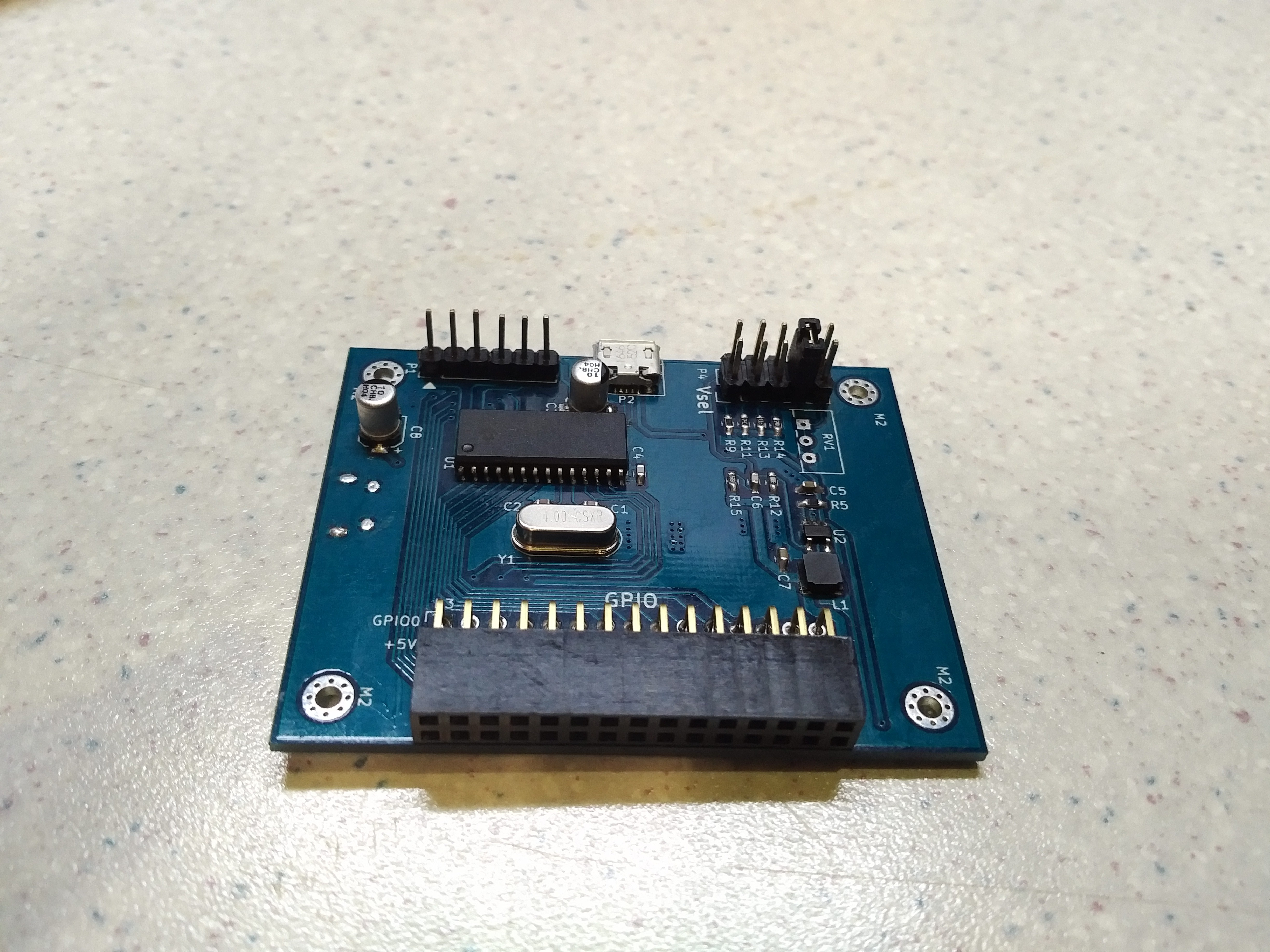
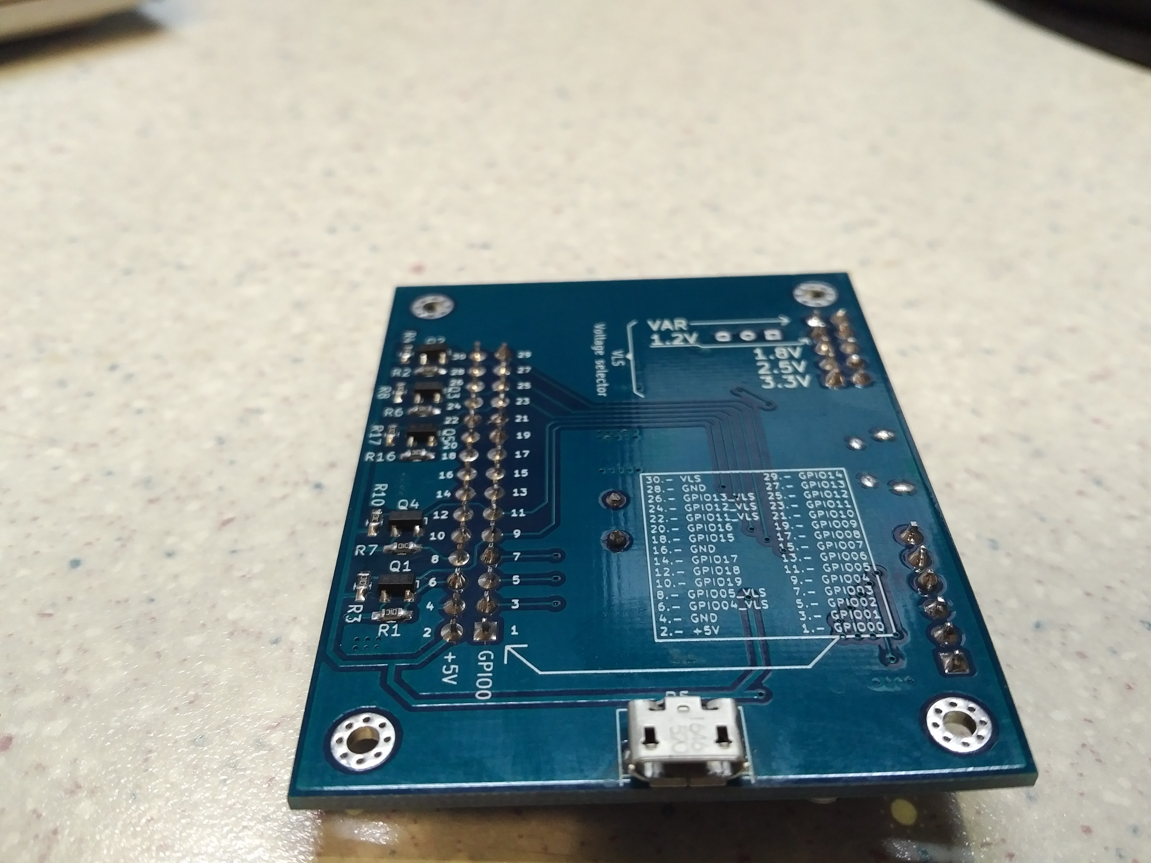
Finally this is the board with almost all soldered:
![]()
![]()
Finally I inserted the PicKit 3 on the ISCP port and I see another problem, the capacitor C3 get in the way of the PicKit 3:
![]()
Anyway the AccessB PIC was programmed without problems and was enumerated by the USB por of my laptop and detected by my test software, the next steps will be:
- Check if AccessB Voltage Level Shifter Works and communicate with a SPI/I2C Devices at 3.3/2.5/1.8/1.2/0.8 volts.
- Change the SOIC28 Narrow to Wide.
- Change the position of C3.
- Point out on the silk screen that P5 (USB micro port) is used only for power and P2 for data and power.
- Update the Hackaday.io project
So there is some work to do, see you on the next days.
-
MPLAB XC8 v 1.32
04/28/2016 at 21:35 • 2 commentsWell a little update, if you want to edit/compile without problems this project on MPLAB X you will need to download the old 1.32 version of XC8 to compile the proyect, I had the 1.36 version of XC8 and it don't have plib.h file needed to do some flash erase/write routines, I dont know if the newer version 1.37 of XC8 have the file, I must to try.
So, you can use the actual version of MPLAB X v3.26 with XC8 v1.32 to compile the project.
I still waiting to get the funds to order the PCB from OSHpark, so this project isn't dead.
-
It's matter of time...
01/11/2016 at 23:32 • 0 commentsHi to all.
Well the project will be stopped for undefined time, yes it's almos done (I only need to order the PCB from Oshpark to end this project) but I don't have the money for now, (well I have it but also I have priorities like wife and daughter), at least I bought all the parts on last December from Digi-key for making three boards, when I have the PCB from Oshpark I will update the log with the good news.
-
Change to KiCAD
12/07/2015 at 23:30 • 0 commentsThis project was a really good reason to learn to use another PCB design tools, and I opted to use KICAD for designing the final board, it was hard the first days with KICAD (I always used EAGLE) but nothing that google FU can solve.
For now I can upload the KICAD design files on GitHub but I will upload to google drive until I can access GitHub.
-
GitHub files update
11/14/2015 at 22:19 • 0 commentsHi to all.
On the last update, I change the way of how the methods pass the data to write/read file functions on winusbapi.cs, before the user must declare an byte array of 65 bytes with the value in array[0] = 0 to work properly, this must be hardcoded by the user, I change that so the user declare the most "regulat" 64 bytes array containing the data to be send or to be read, read/write functions will concatenate the 64 bytes array with a 65 bytes array with array[0] = 0 this is more practical but some methods stop to work and I don't solve it in that moment, now that problems are solved ( I hope so) but also I made another changes:
Related to ADC methods change some variables from UInt16 to UInt32.
Related to ADC_Val method I change the way of how the data is returned to the user.
About the new PCB design, Jarrett tell me to use a PIC-controlled buck regulator, but I don't want to add another uC to this board, but the buck idea likes me, so I will use the MCP1306 in its adjustable version to obtain all the voltage levels that I want, here is a document about an evaluation board that I will use.
Well I need to go now, hasta luego!.
-
Finally UDF!!
10/28/2015 at 05:22 • 2 commentsFinally I implemented UDF in C# class files (AccessB_class.c, AccessB_winusbapi.cs) and the MPLAB X project, now if you want to make your own custom function to be included in AccessB you must open the MPLAB X project and write the code inside the UDF function on the UDF.c file and compile the entire project, then use UDF programmer to open the hex file and click program, it will extract ONLY the UDF opcodes and then it will program all the program data on the 18F2550, you can after call the UDF using the CALL_UDF method.
UDF support ISR but low priority only, this because high priority interrupts are used by USB module, setting another high priority interrupt source may cause unexpected behaivor on the USB module.
Another update on the C# class files are the GPIO methods GPIOx, GPIO_DIRx, GPIO_LATCHx give access to PORTx, TRISx, and LATCHx SFR but in a more general way, more experienced PIC uses may prefer to use the TRIS/PORT/LATCH (that is a more direct and fast way to access I/O) and lees experienced PIC users may prefer to use GPIO, well I don't want to enter in to details now so I will make an user guide :)
The next stage is to design a new PCB, this will include voltage level shifting from 5v to 3.3V / 2.5V / 1.8V / 1.2V in five I/O corresponding to SPI/I2C/USART, and all will be SMD in a double layer PCB.
All the projects now include the update versions of the C# files, also I included the link to the GitHub repo of the UDF programmer.
-
UDF almost done!
10/05/2015 at 19:25 • 0 commentsUDF is almost done, it need to refine details, for now I tested simple UDF that only change the value of LATB register from 0xAA to 0xBB and viceversa with success, I need to test low priority interrupts with UDF and send/receive data over USB inside the UDF, may be a couple of days more and the software/firmware part of this project will be completed!!..
The next step will be redesign the board and include logic level shifting to SPI/I2C/USART pins, to interface 5V to 3.3/1.8/1.2 volts.
When all the UDF part be finished I will upload the source files to GitHub.
-
Working on UDF.
09/03/2015 at 22:41 • 0 commentsIt's been a while without updating, but there are a good reason: the birth of my first daughter, but even so I've been working on UDF (User Defined Function) part of Access B.
After thought for a couple of days I made the decision of don't make a JTAG routines as I had mentioned before, I want to end this project and pass to another projects using the Access B. JTAG can be implemeted through UDF anyway.
I will redesign the board to include a logic level trasnlator for SPI, I2C and USART (5v to 3.3v).
-
Upload to GitHub
07/10/2015 at 20:05 • 0 commentsWell I uploaded some of the source files and project to GitHub, the source files from microchip still be in google drive for a couple of days and then I will move to GitHub too.
The AccessB MPLABX project compile with no errors but there is some issues:
- The problem with SPI that I mentioned before was resolved.
- I'm working on EUSART module firmware and class code so isn't work correctly.
Access B
Create applications in Visual Studio C# that can communicate with a 18F2550 and use it's peripherals