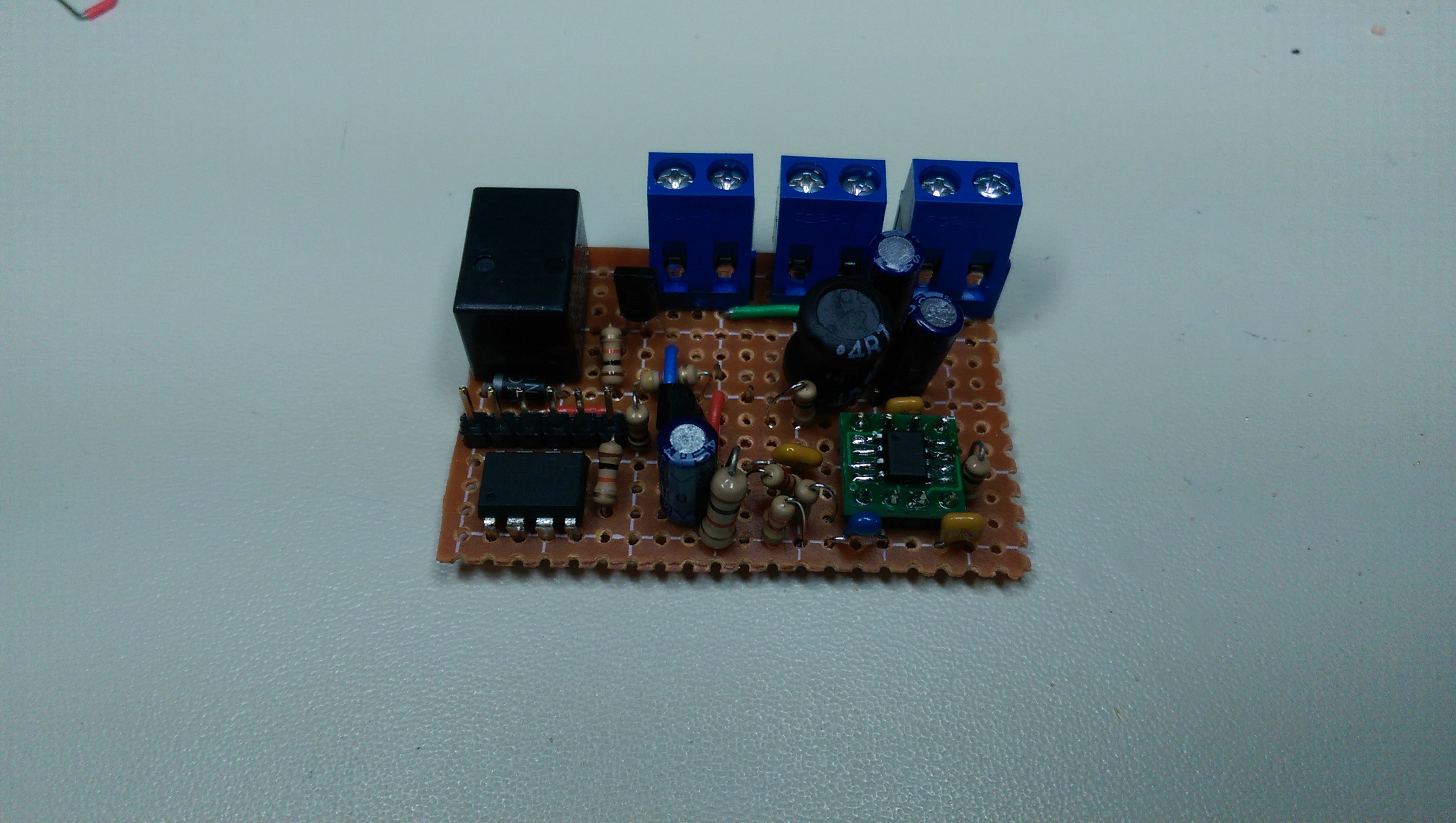
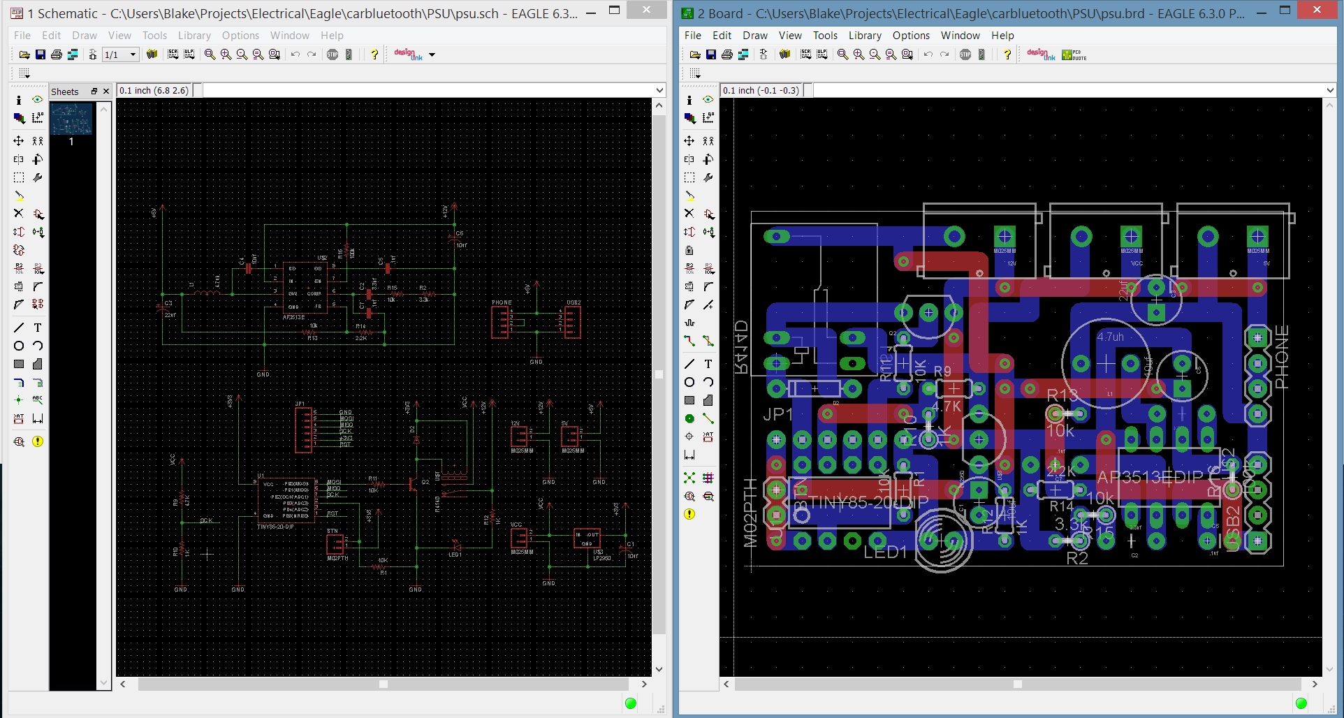
Sorry for the lack of updates, I have been busy with other things and working on the power supply. During that time I have added a buck converter to the circuit for USB, and soldered it all onto a piece of perfboard designed in Eagle.


While it all works, it can still be improved. I soon realized that I did not need to break out all 8 USB pins (2x4), when only two were necessary (power and ground). There was also an issue with the placement of some components on the board blocking other parts. I did not take into consideration that the parts sticking out of the enclosure (button, power input, etc) would also take up additional space inside of the case. I had to re-cut a few holes as a result, and then cover it all with white paper (???????????). I also hot glued the USB ports to the cover, which caused the "springs" in each port port to become stuck. This increased the amount force necessary to plug/unplug USB cables from the power supply, enough to worry about pulling the ports out. Fortunately, nothing has broken yet.

But after much testing and tweaking the code, I think I can finally say it is more or less ready for use. It isn't exactly pretty, but everything works as intended and should be decently protected in its case. It turns on/off when the car does, charges my phone at 1 amp, and can be overridden when the car is off. The button I used is kind of lame, but I don't want to buy a better one if I don't have to.
As for the next part of this project, I am currently waiting for parts I ordered (almost a month ago) from China to arrive. I forgot about how the Chinese New Year tends to make everything there stop for a few weeks. I will be able to continue this project as I receive more parts to experiment with (which are finally starting to come in), and adjust plans accordingly.
 HybridAir
Discussions
Become a Hackaday.io Member
Create an account to leave a comment. Already have an account? Log In.