I have taken a break from this project for personal reasons, but I am finally getting around to bringing it back from the dead. During that break, I have taken some time to think about this project. I have realized that I can replace most of the current system with a Raspberry Pi A+. I decided to go with this new method for a few reasons:
- Tons of community support, less going through obscure Chinese forums trying to find specific datasheets
- Capable of handling more than just bluetooth
- $20
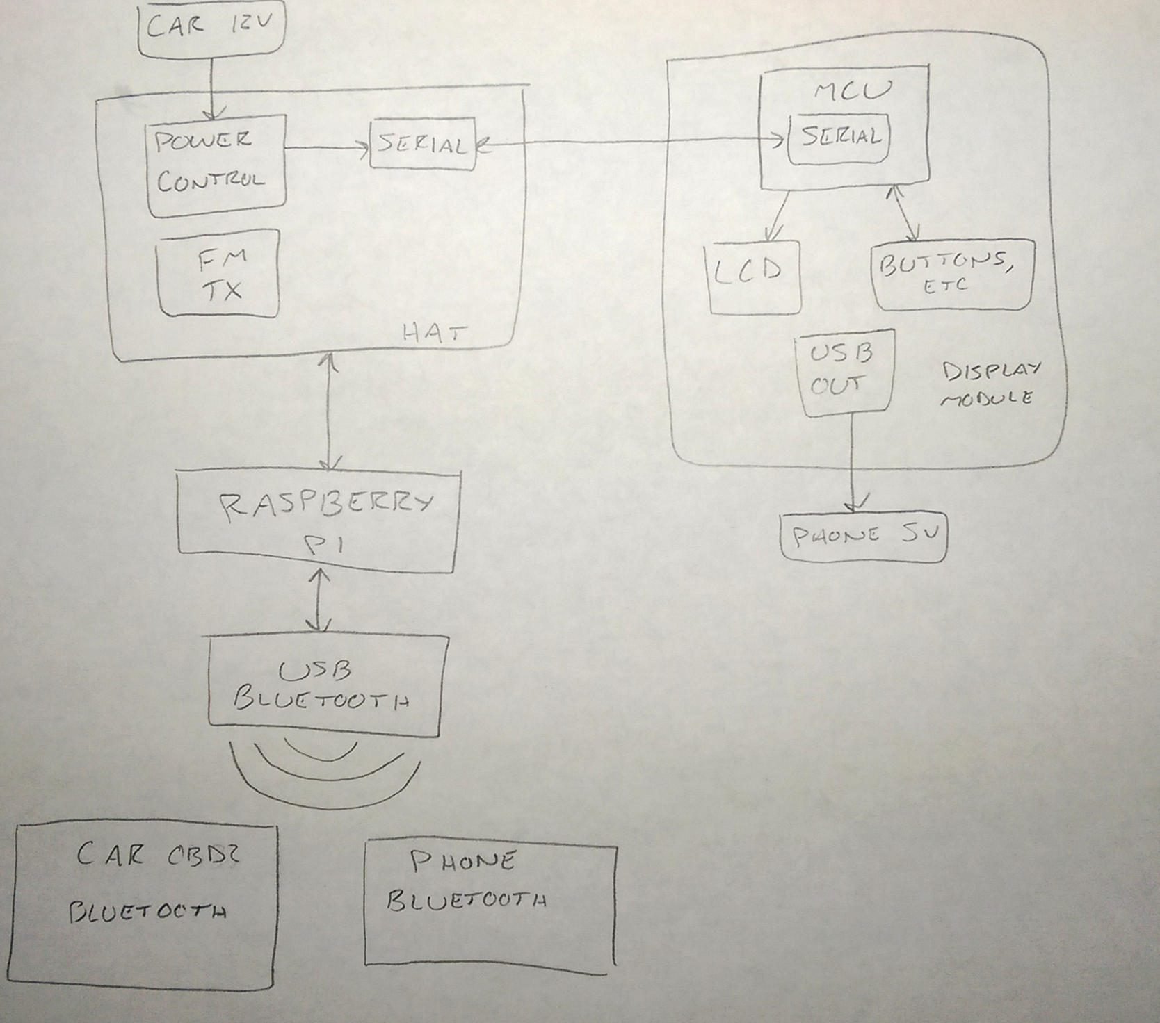
Bluetooth connectivity will be made possible with your average USB bluetooth 4.0 adaptor, using the CSR8610 SOC. The Pi will handle music streaming, control, and song data processing from the phone. The Pi should also be able to get data from my bluetooth OBD2 scanner, and do things with that. It will transmit the music over FM radio to the car using either PiFM, or more likely, the QN8027. The power supply/controller, fm transmitter, and other related devices will be located on a custom Pi HAT or something. For some reason I never posted how I found out about the QN8027 here (except on twitter), so I guess I will do that now.
Back in February I decided to take a look at the inside of my current FM transmitter to see how it worked, and to find out what it used to transmit FM radio. It was filled with vague and unmarked ICs. Fortunately, after some guessing and searching, I ended up with the QN8027.
According to this datasheet, the QN8027 is an FM audio transmitter. It can be controlled over I2C, supports RDS, and comes in a package that isn't impossible to hand solder. I found a few suppliers on aliexpress that sell them, so I quickly bought a few for testing. At first I tried deadbug soldering it, since I had no msop10 breakouts on hand. Don't do that if you value your sanity, and want something that doesn't end up breaking soon after. I ended up buying some breakouts. I will be honest, I have almost no idea what I am doing when it comes to RF witchcraft. Somehow though, I managed to make it work.
Anyways, music playback control and song data display will be handled by the "display module". This device will communicate to the Pi over serial through a USB cable, but USB itself will not actually be used. I am using USB because I don't want a long strand of dangling wires just leading from the Pi up to the display module, or some weird proprietary cable. The display module will have a USB output for charging the phone, though. Because of the reduced workload and IO requirements, I could probably get away with using a lower power/cheaper MCU for the display module.
Perhaps a block diagram will help explain things better:

 HybridAir
Discussions
Become a Hackaday.io Member
Create an account to leave a comment. Already have an account? Log In.