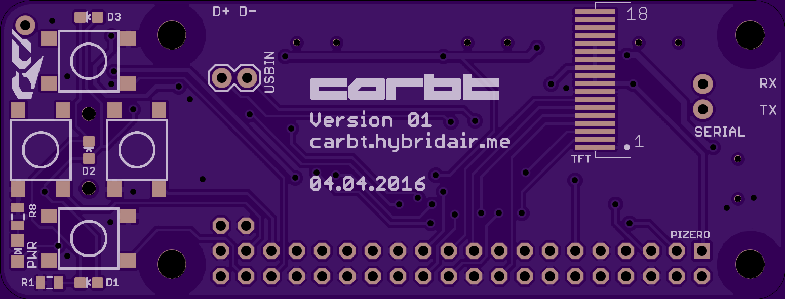
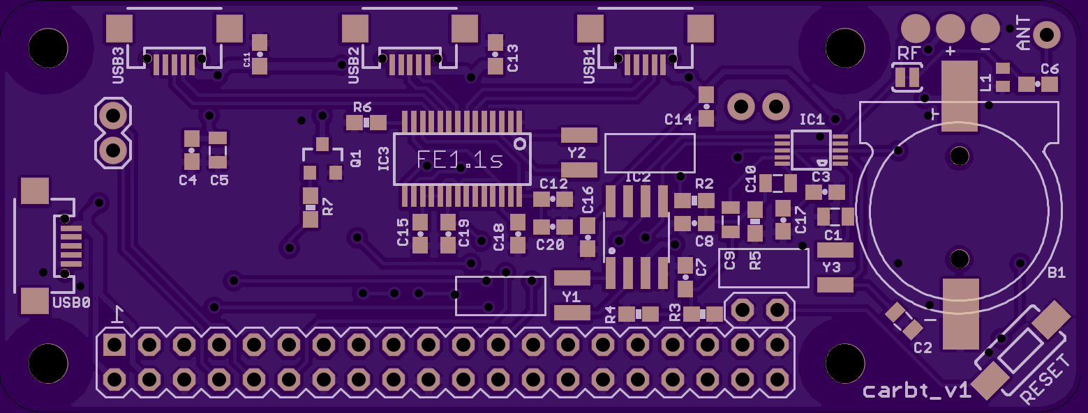
I have finished designing the PCB, and have sent off the design to OSHPark to be made. Have a look at the final design below!


I also posted a rough 3D model of the project on sketchfab, to give you a better idea of what the complete device will look like. The textures are broken, but the overall model is correct. Unfortunately, some design compromises had to be made to get everything to fit without making the board too big.
First, the Pi Zero is going to be directly soldered to the carbt PCB. While using removable male/female headers would be nice, it ended up making the whole thing too thick. Given that the Pi Zero is very cheap, and its purpose in this project, being permanently connected shouldn't be an issue. Access to the SD card, serial pins, USB, and HDMI is still possible.
For the USB hub part, micro USB ports are used instead of full-size USB A ports. This is very similar to how the Pi's host USB port is designed. The full-size USB ports are too thick, and require significantly more PCB surface area than the micro ports. Small and inexpensive adaptors will be used to provide compatibility for standard fullsize USB devices. The USB bluetooth adaptor is shown in the sketchfab model as an example. As for connecting the HUB to the Pi itself, two leads will be soldered to the USB test pads on the pi, which then connect to two pins on the carbt.
The RTC's battery was placed in an easily accessible location, on the side of the PCB that is not covered by the Pi. Pads for the FM transmitter antenna are also exposed on that side. The user has the option of using the built in "antenna" circuit, or directly connecting their own antenna (with an amplifier, if desired). A solder-jumper has been provided for switching between antenna types.
The primary buttons on the front of the device have a few dimmed white LEDs near them, to easily locate them in the dark. An additional brighter green LED is used to signify when the device is powered on. There is a smaller button on the backside, used for resetting the Pi in the event it locks up. Since the whole thing will be running off a read-only file system, using the reset button should not have any detrimental effects.
Due to time constraints, I was not able to implement the auxiliary audio jacks, or sensors. Those will need to be saved for a future version 2. Other than that, I was able to include almost everything that I wanted to, and am very satisfied. I will post an update once I receive the boards, and when I am able to start assembling it all.
 HybridAir
Discussions
Become a Hackaday.io Member
Create an account to leave a comment. Already have an account? Log In.