 smashedagainst
Got in a dedicated CAN bus arduino shield, so I'll make the next steps using that (and the existing working code on the net).
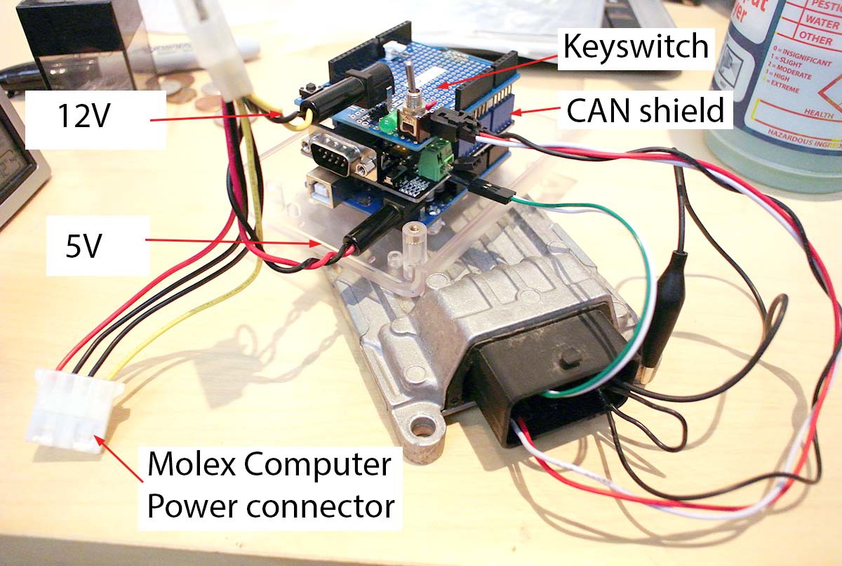
The power comes from a "PC - like" supply that feeds 5V and 12V to a molex connector. ECU is a Continental / Siemens M3C ecu bought off eBay.
Top board ties together the grounds and that's the only link to what's below. The board is an arduino-branded "prototype shield" that I use for tying together random things. The top shield accepts the 12V and then sends it to the red wire. The switch sends 12V to the white wire and simulates when the ignition switch. And this 3 pin keyed connector also supplies ground to the ECU, where it splits into the two required grounds (female clips) and the alligator clamp for grounding the case.
CAN shield is from Seeedstudio and has two female headers plugged into the green CAN connector: as shown, it's only attached to the ECU and the separate header allows this to be inserted in between other nodes (say the ECU and diagnostic equipment).
Arduino aka the board on the bottom, is actually an Arduino Uno. I'm using it solely because there's so much example code based on it. Once I've figured out what I want to do, I'll move on to other platforms.
This is the sketch I started with but I'm pretty sure it was ignoring unknown PIDs plus it probably wants the legacy 2.x python as it didn't work on the latest version. I'll try Seeedstudio's sample code next.
Discussions
Become a Hackaday.io Member
Create an account to leave a comment. Already have an account? Log In.