Earlier I had mentioned that the current limit LED indicator was not working properly. It would work when current limiting was enabled for very low values (less than 100mA or so), but it would not turn on for higher values.
Today I ran through the entire current limiting control circuit, and figured out what was happening.
The issue occurs because the current limit control output from the op amp does not go higher than about -0.1V for the majority of current limit setpoints. (Given that I am using a PNP transistor for current limiting, that makes sense). The op amp that I was using to turn on the LED was comparing this value to GND; obviously, if the current limit output does not go higher than GND, it will never turn the light on.
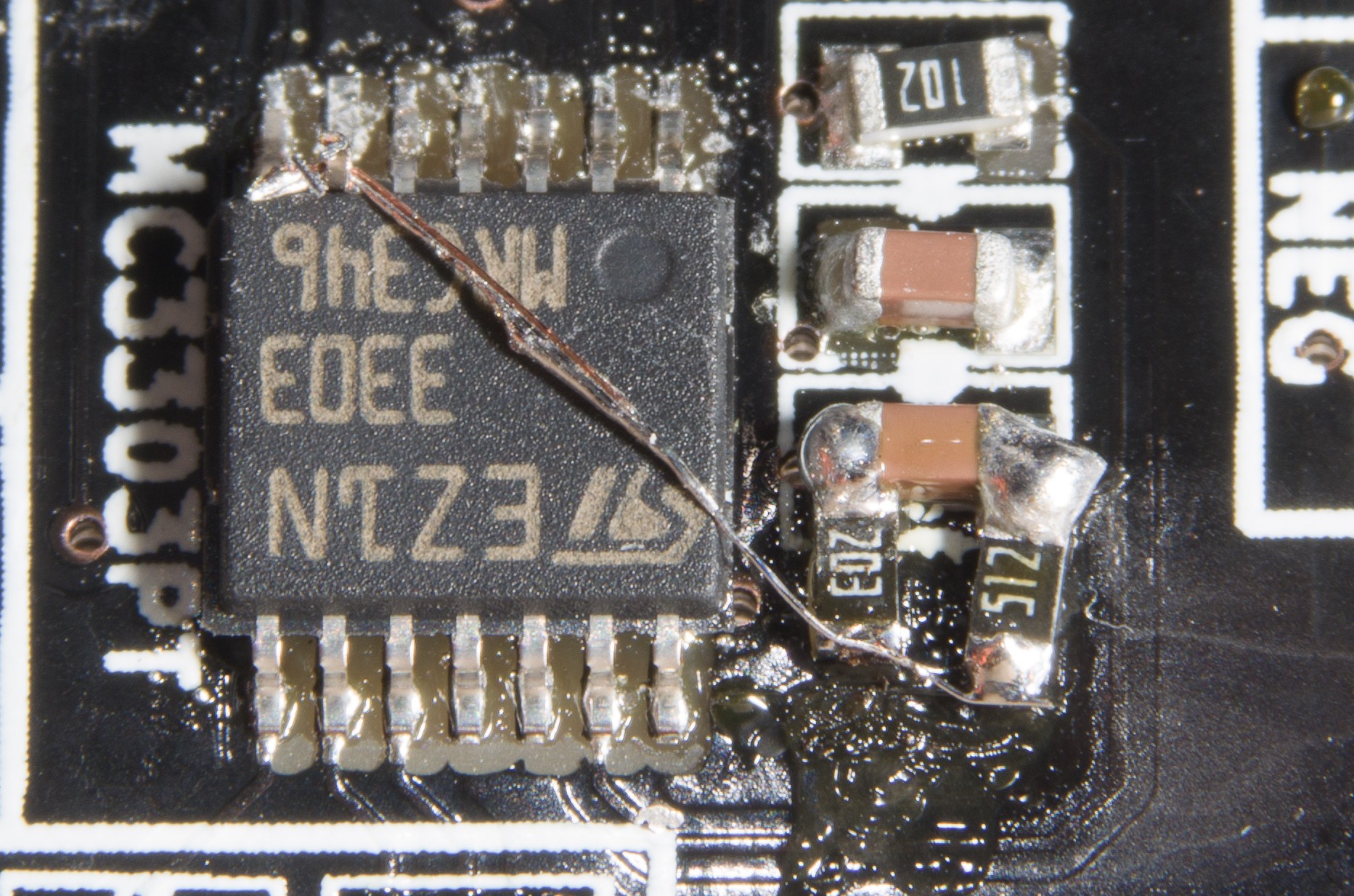
To fix it, I soldered up a voltage divider to get about -3V, and used that as a comparison value rather than GND. Very simple, except that it was reworking an SMD board. I had to lift an op amp pin and solder a jumper between it and the voltage divider output. Luckily there is a decoupling capacitor very close to the op amp which provides me access to -15V and GND in a tidy 0603 package.
WARNING: The photo of the result is below, and looks hideously ugly. Do not view this photo if you have a heart condition, are pregnant, easily scared, suffer from (or enjoy having) OCD, or think that a 1/8W axial resistor is small.

For scale, the resistors / caps are 0603 and the IC is TSSOP-14.
Unfortunately, I didn't find this until the third board, two of which are already in the enclosure. I guess I need to take them out to do this fix... that will be annoying. :-(
For those following along at home, Rev 1.1 boards will include the proper voltage dividers on the board itself (I just need to figure out if anything needs to change for the negative boards... that will be my next mini project).
 The Big One
Discussions
Become a Hackaday.io Member
Create an account to leave a comment. Already have an account? Log In.