Per resounding request...
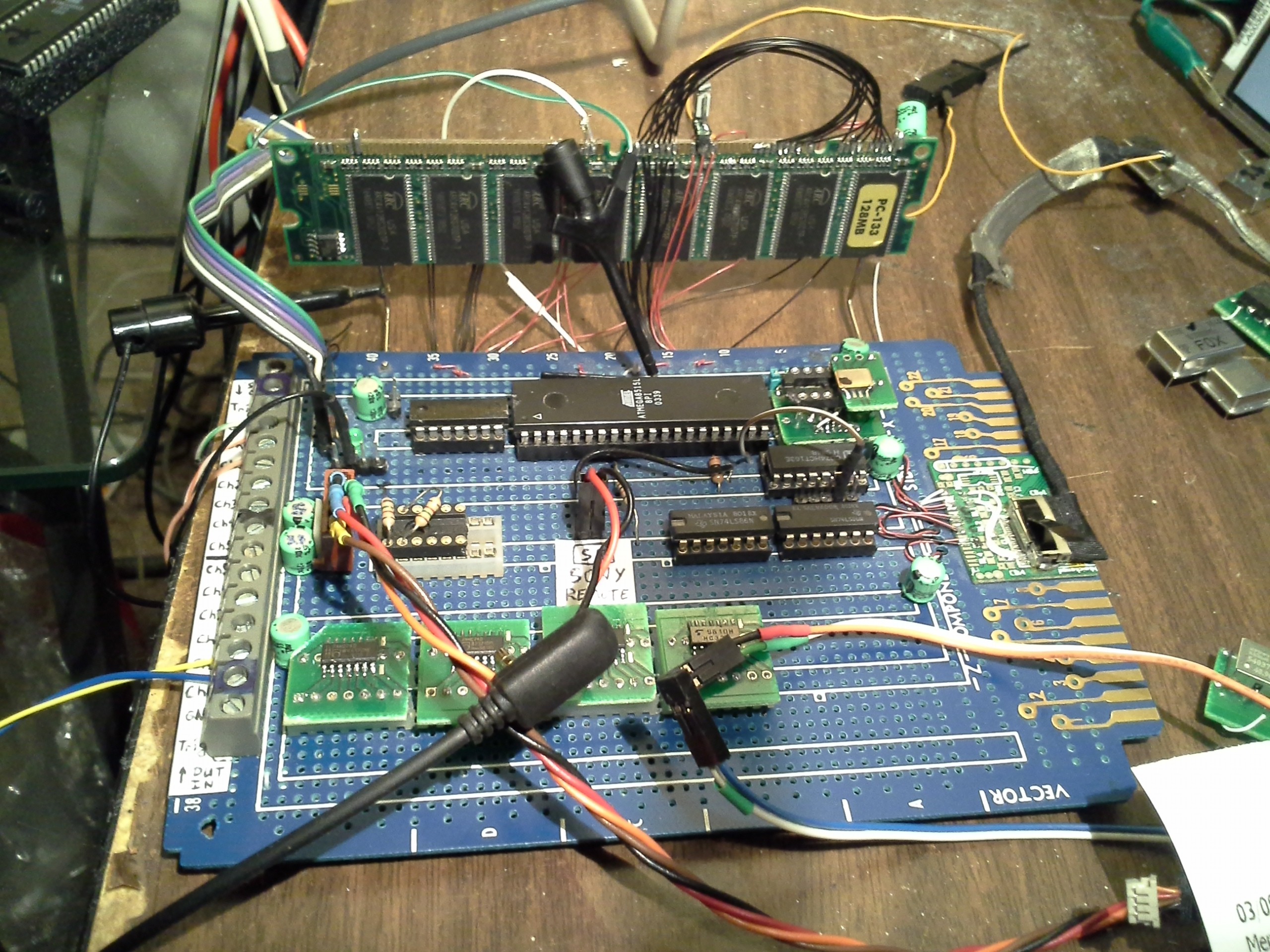
sdramThing4.0:

Chips, from left-to-right, top-to-bottom from under the SDRAM DIMM:
- DM74H51N AND-OR-INVERT used as a multiplexer, of sorts, for the Chip-Selects and Enabling-thereof
- ATMEGA8515L-8PI (Atmel AVR, rated for 8MHz, has run up to ~20.5MHz!)
- 30MHz Crystal Oscillator stacked atop a CY2305 Clock Buffer (both found on an old dead TV's PCB) mounted on a SMT-to-DIP breakout board (see below)
- CD74HCT163E 4-bit binary-counter used to divide the Oscillator's frequency for the AVR (currently /2)
- (There's a couple resistors in the next socket, these help separate the input/sampled data from the output/repeated data on the same SDRAM Data pins).
- SN74LS86N (x2) XORs. These are used as Buffers/Inverters to drive the LVDS signal used by the LCD (the LCD connector is to the right of these chips)
- 74HC74D (x2) Flip-Flops used for the new one-shot circuitry (found on an old Pentium I Laptop's mobo)
- 74HC08D AND used for the Chip-Select one-shots (ditto)
- 74HC32A OR used for the DQM one-shots (ditto)
Atop the DIMM is a two-position (three-pin) jumper, used to select compatibility with software for sdramThing4.0 or sdramThing3.5 and below. This reroutes one chip's DQM differently so that the LCD's Blue (and Timing) data can be modified without having to recalculate the Free-Running commands, nor the LCD's clock. (The LCD's Blue/Timing Data, as well as the clock, is on the "Free-Runner" as that data--the cursors and status-bar--remains constant regardless of new samples). This change, mainly, was an attempt at allowing for changing of the blue-data despite the "double-write" issue, from before. Though it's a useful feature I'd had on the backburner, regardless.
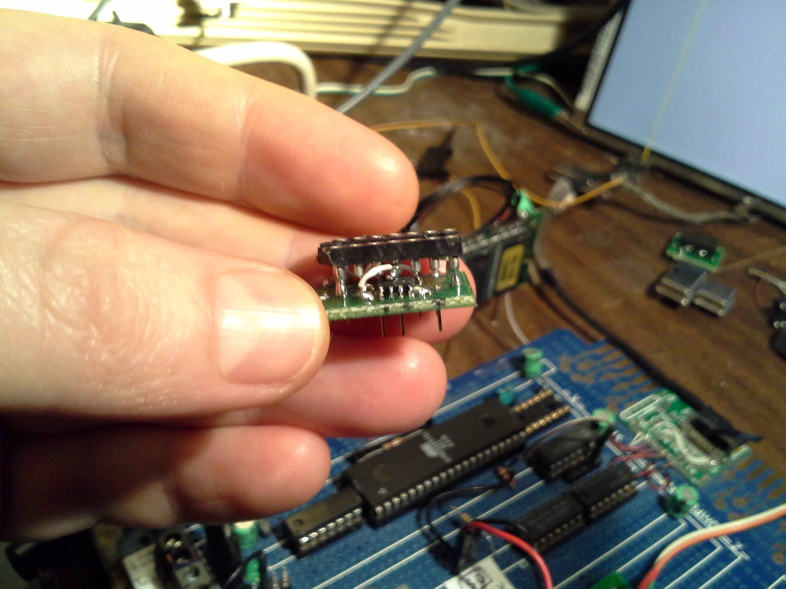
Clock Buffer Breakout-board:

This guy fits in the original crystal-oscillator socket (seen in the background, right of the AVR)--with just a few rewires--and adds 5 buffered clock outputs... Handy... Some of my oscillators don't have the drive-strength for 8 SDRAM chips, the clock-divider, and 4 Flip-Flops.
ALSO: It has a 5V-tolerant input! Also handy, some of my oscillators don't play well with 3.3V. Next to the socket, in the background, is a three-pin two-position jumper for selecting 3.3V or 5V to drive the oscillator, which now gets attached to the top of this breakout-board. Also, this handles both 14-pin-spacing oscillators as well as 8pin. WEE!
Below: The latest sampled-data from the motor-driver...
(Apparently my uploading didn't go in order, and I daren't copy/paste these, as it'll likely take forever to reload them on my flaky 'net connection)

The upper trace(s) show, I presume, the clock-signal. The lower trace(s) show, I presume, the data-signal. (There seems to be a new bug in sdramThing4.0, the horizontal lines shouldn't be there). Otherwise, it *looks* about right, by which I mean the clock appears to be toggling at roughly 50%... I forgot to check the timing on my 'scope, but some of those toggles look a little skinny. I'm not sure the cause... But, it's plausible the toggling-rate is actually, still, slightly faster than my 30MS/s sampling. This *might* be corroborated by the fact that I'm counting, at best, what appears to be a pair of 16-pulse trains... Yet, as I recall, the *similar* but not-identical motor-driver I have specs for claims 18bit packets. This is why I wanted to sample this thing... I don't know if this chip uses the same data format as the other. That, and... I didn't quite understand what the registers *do*, especially on initialization. The *other* chip has some strange (to me) settings related to current-output, drive-strengths, and whatnot that I just can't parse from the data-sheet.
This packet is the first seen in the image below.
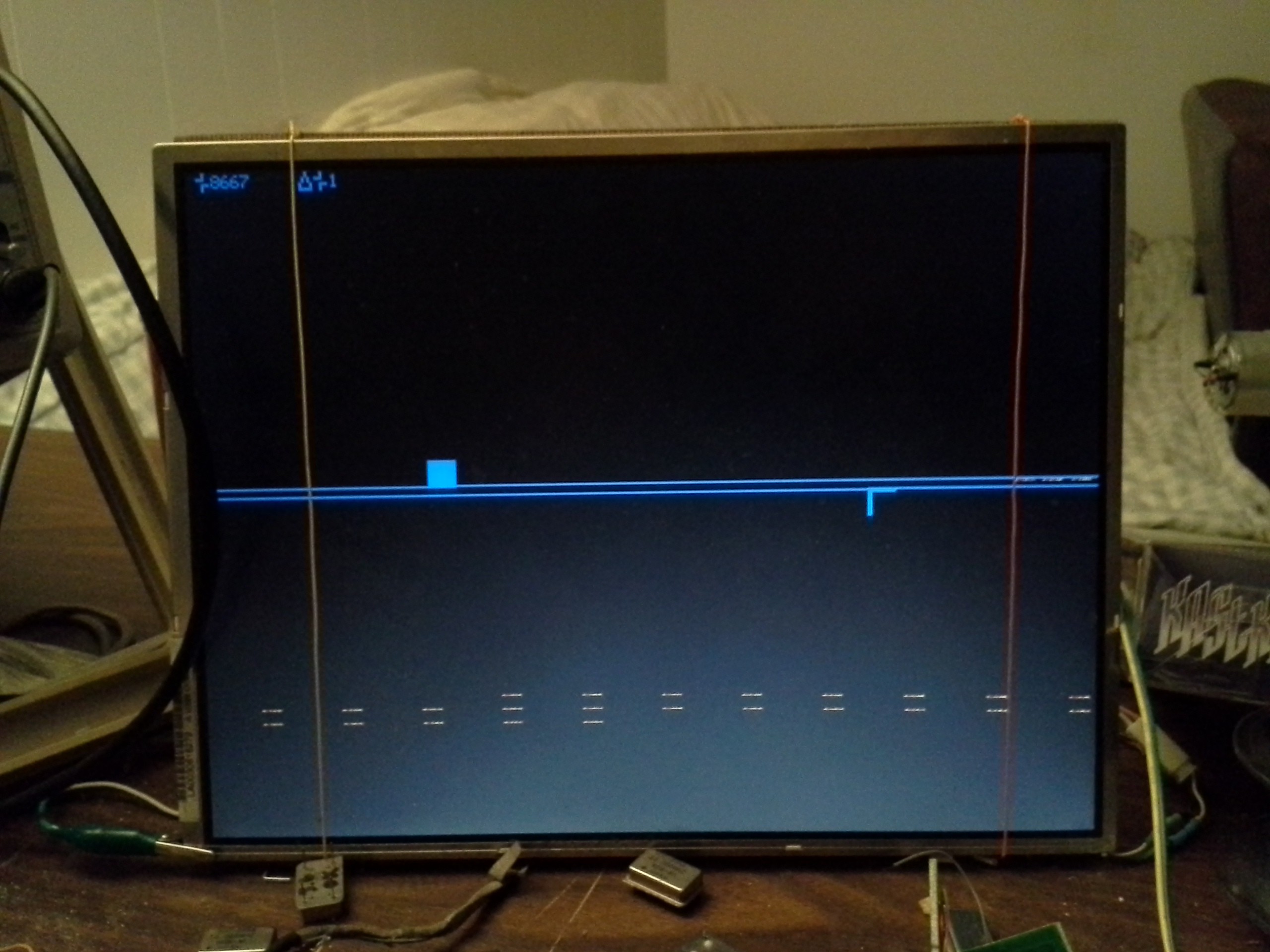
Below: The entire data-sample is shown on sdramThing's display in raster-fashion.

Two channels are currently in-use, corresponding to the two channels on my 'scope. One is shown on this display as Red and the other is shown as Green. Each pixel represents 7 data-samples. The cursors are (roughly) selecting three data-packets. The first packet is shown on the 'scope traces, shown earlier.
The status-bar, at the top, shows the number of samples between the cursors, as well as a "Delta" value for requested cursor-movements.
The cat found a good pillow...

 Eric Hertz
Discussions
Become a Hackaday.io Member
Create an account to leave a comment. Already have an account? Log In.
Thank you for the pictures! I now realize the burden they are for you, sorry to pressure you :( I wish they will benefit others also :)
Are you sure? yes | no
No pressure, I'd been meaning to anyhow, and it's a good idea in general. Thanks for--not pressure but--the motivation!
Are you sure? yes | no
Nothing like a warm security multimeter :)
Are you sure? yes | no