Close
0%
0%

LVDS Laptop Display Interfacing

A journey into re-purposing old laptop screens

Similar projects worth following
This project is an experiment into the world of LVDS laptop screens. Long thought to be not possible or easy, I will show it is actually quite easy!

So far I have successfully used two LCD panels:
An old fluorescent-backlit LCD panel out of a Toshiba PT200A
A transflective(!) LED-backlit LCD panel out of a Toshiba Portege R500

You might think that interfacing to a laptop LCD is not easily possible - laptop LCD panels do not provide an HDMI, DVI, or VGA interface, as they are intended to be wired directly into the laptop's graphics controller. However most laptop panels use the same interface: LVDS (Formally known as FPD-Link or FlatLink), and the protocol itself is very basic requiring no configuration of the panel, only requiring that the graphics controller is configured for the correct resolution!

Here, I will document my experiments with various laptop LCD panels that I have.

Instead of converting LVDS to a more usable protocol like HDMI/DVI, I am using a RIoT board which has a native LVDS connector, making it very easy to connect a panel!

Eventually I am thinking about writing an article documenting everything you need to know in order to re-purpose an old LCD panel. Let me know if you would be interested in this!

  • Working Prototype

    Jared Sanson03/16/2015 at 08:56 0 comments

    I've pretty much got my R500 LCD panel working how I want it at this stage, so I probably won't look at any more panels for now. I've definitely learned a lot about how LCD panels work though!

    Continuing on from my last post, I managed to solve all the issues I had:

    • Messed up colours
    • RIoTBoard & EDID
    • Configuring the RIoTBoard's output resolution
    • Backlight Driver

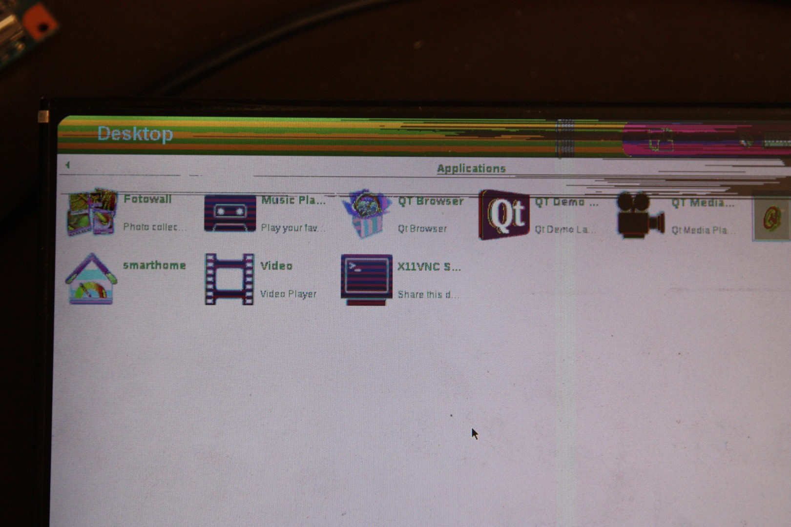
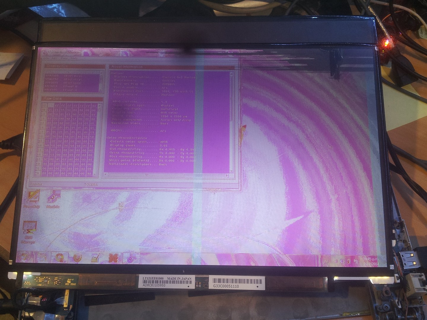
    Firstly, the messed up colours was a pretty easy fix - I had two of the LVDS channels mixed up because the wire colours were very faint and hard to distinguish. After swapping them the display worked beautifully!

    Secondly I wanted to know whether the RIoTBoard could make use of the display's built-in EDID chip, which contains information to tell the host computer exactly how to drive it at the correct resolution. Unfortunately it seems my build doesn't implement EDID (at least not within U-Boot), so I was forced to hard-code the resolution into U-Boot env. This isn't really an issue since I intend to only use this display with the board. Interestingly I can indeed read the EDID info within user-space once I'm in linux.


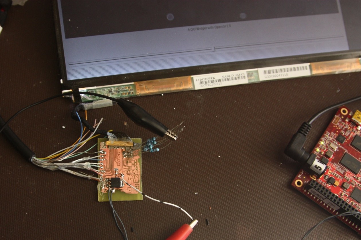
    Finally I wanted to implement the backlight driver. This took a lot more effort than I was expecting, as the circuit turned out to be very unstable, and my poor selection in components caused excessive overheating. It took me a bit of trial and error to find an appropriate MOSFET, diode, and inductor that would work at the high frequencies that it was operating at (~500kHz). I did manage to get it working in the end, with an unholy amount of bodge-wires:

    I might have a look at some more LCD panels and driving methods in the future, but it looks like I'll be focusing on the Hackaday prize for now!

    If you'd like more information about anything here, I'm happy to share.

  • Breaking it out

    Jared Sanson02/05/2015 at 07:25 2 comments

    The next big problem I have with the Portege LCD is that the connector is tiny and it's not possible to solder wires to it. So I started making a breakout board for it:

    It was very very tedious work, and in the end it didn't even work :( Somehow the wires inside the connector shorted through to the case.

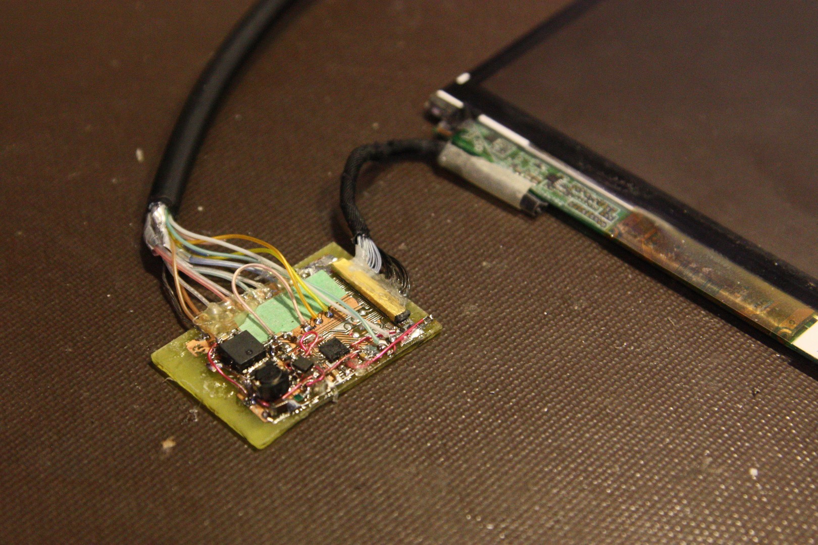
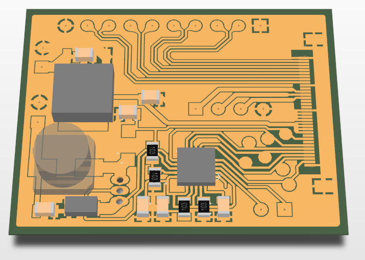
    So I decided I should do it properly and make a breakout board, complete with backlight driver. To reduce the risk of things going wrong I decided to use the same backlight driver chip as the laptop (MAX8790 6 channel LED driver)

    Because I was feeling impatient I decided I would try to etch it at home instead of ordering online, so I designed the PCB to be single-layer with only SMD components. The LVDS signals are routed through to larger pads to make it possible to solder, and there's also some breakout pads for the EDID I2C lines as well.

    I wasn't actually sure if it was possible to etch a PCB with traces that fine (the SMD connector pitch is 0.4mm, and the LVDS traces are 0.254mm wide!!), but I wanted to give it a shot anyway!

    It took me 4 attempts to actually get the iron-on toner transfer to stick properly, since the first few times I overheated it and melted the plastic sheeting, but in the end it paid off!

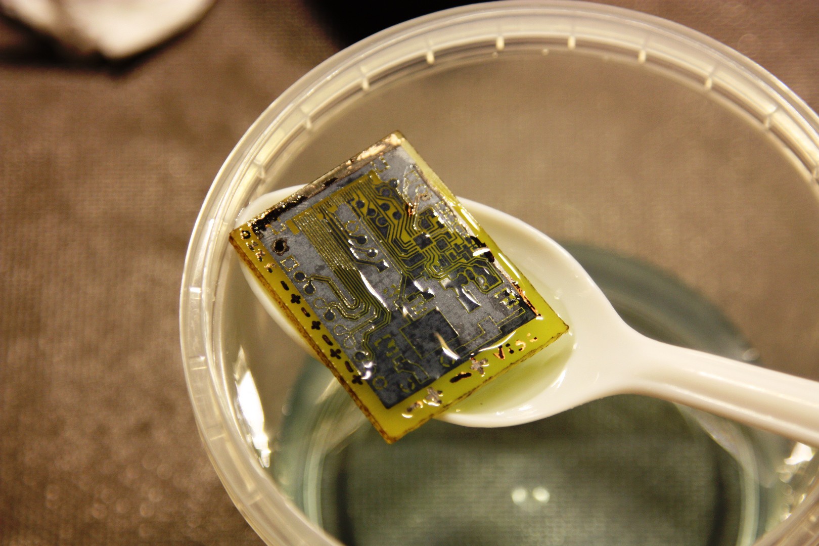
    I then etched it in an ammonium persulfate solution:

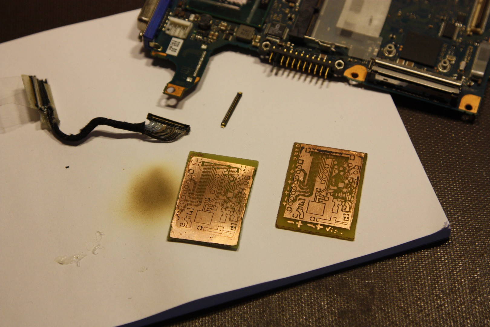
    Although it looks perfect, the etchant had gone way too far and had eaten all the LVDS traces, which you can see in the next photo (the PCB on the right):

    Fortunately my second attempt was almost perfect! (Apart from some microscopic shorts which I managed to remove with a little bit more etching)

    An interesting note I found about using ammonium persulfate: You must have the solution (water and ammonium persulfate crystals) in the right proportions! Too weak or too saturated and it won't etch properly! This caught me off guard because I naively thought a stronger solution would just etch it faster, but there must be some chemistry happening when the solution becomes completely saturated preventing it from doing anything at all.

    After some quick soldering I powered it up and connected it to my RIoTBoard, and much to my surprise it powered up and worked first try! The only flaw being I had two of the LVDS data pairs swapped, so the colours came out a bit funny.

    Project success!

    Now I definitely have plans for this LCD, since it is sunlight viewable! The contrast isn't quite as good as e-ink or the Pixel-Qi display, but it retains colour even in full sunlight, and is definitely usable unless the sun is directly reflecting on the display.

    Still to come:

    • The backlight driver
    • Getting the RIoT board to output the right resolution (note in the first image that there's some empty black area to the right)

  • Reverse Engineering an LCD Panel

    Jared Sanson02/04/2015 at 08:44 0 comments

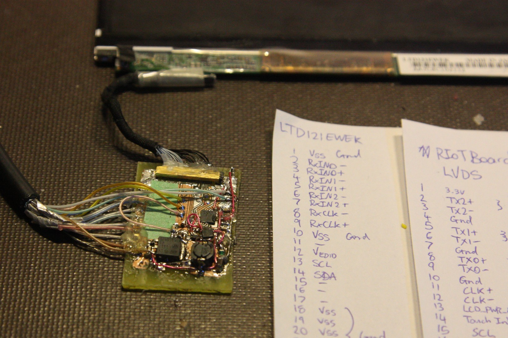
    The next step in this project is attempting to interface a special sunlight-readable "transflective" LCD panel, out of an old Portege R500 laptop. I couldn't find a datasheet at first, so I embarked on a huge task to reverse engineer the pinout by probing the signals in a working laptop:

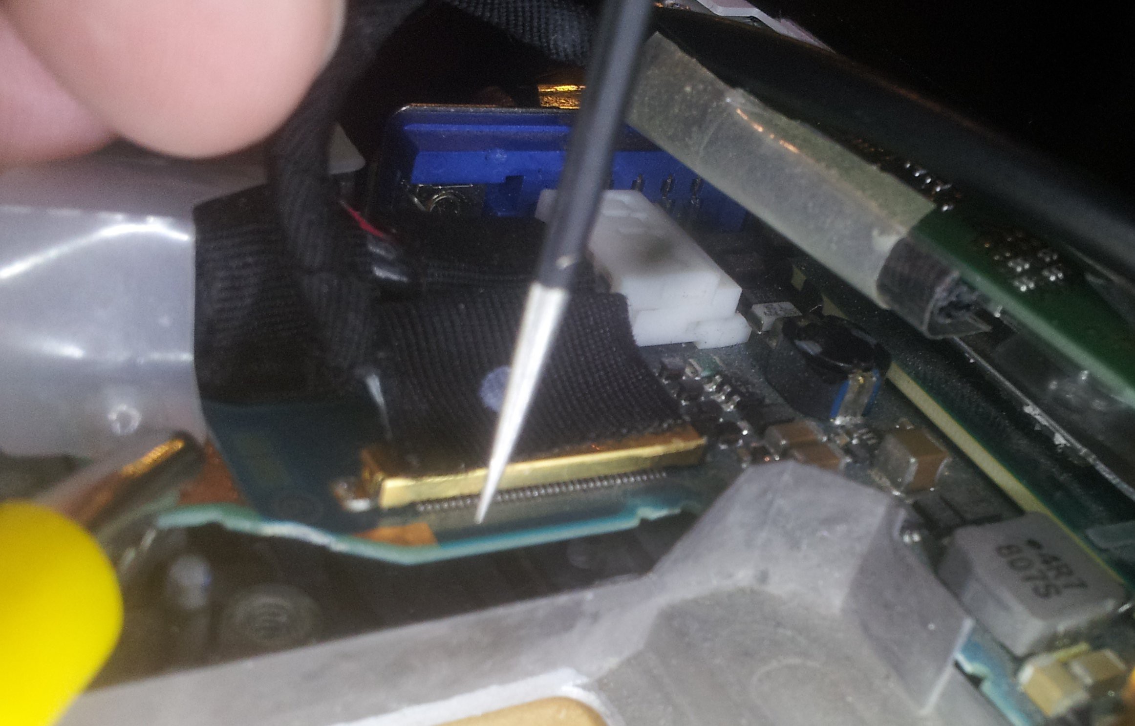
    By carefully probing each pin on that (tiny!) connector, I was able to roughly work out the pinout. The LVDS pairs were fairly obvious as I could clearly see them routed on the PCB, so it was easy enough to trace them back to the connector. I was also able to figure out which LVDS pair was which (Clock and Data) by shorting a pair out to see what effect it had on the display:

    The clock LVDS pair was the easiest to find, as the display simply freezes or goes black when it loses the clock. RX2 was the next easiest, as it contains the HSYNC/VSYNC control signals, so when that line is corrupted the screen loses sync. RX1 and RX0 can be determined by looking at what happens to the colours on the LCD: Shorting RX0 will either cause black to become red, or white to become cyan. Shorting RX1 will either cause black to become green with some corruption of blue gradients, or white to become purple. This all becomes obvious once you look at the layout of colour data within the LVDS signals.

    And then I had one last try at finding a datasheet and finally found one using the serial number on an older model! It turns out I had correctly guessed the power lines and LVDS pairs, but I missed the EDID I2C signals and had the LVDS polarity inverted. Not bad for some fairly simple probing! Having EDID signals also means I can make the display plug'n'play with pretty much any system, so the system will automatically figure out the correct timings and resolution to use.

    My next step is to create a breakout board for the connector, since my first attempt at soldering to the wires failed (the connector shorted out internally due to excessive flexing of the wires. Luckily I have spares!

  • My, What a lot of laptops!

    Jared Sanson02/01/2015 at 04:57 0 comments

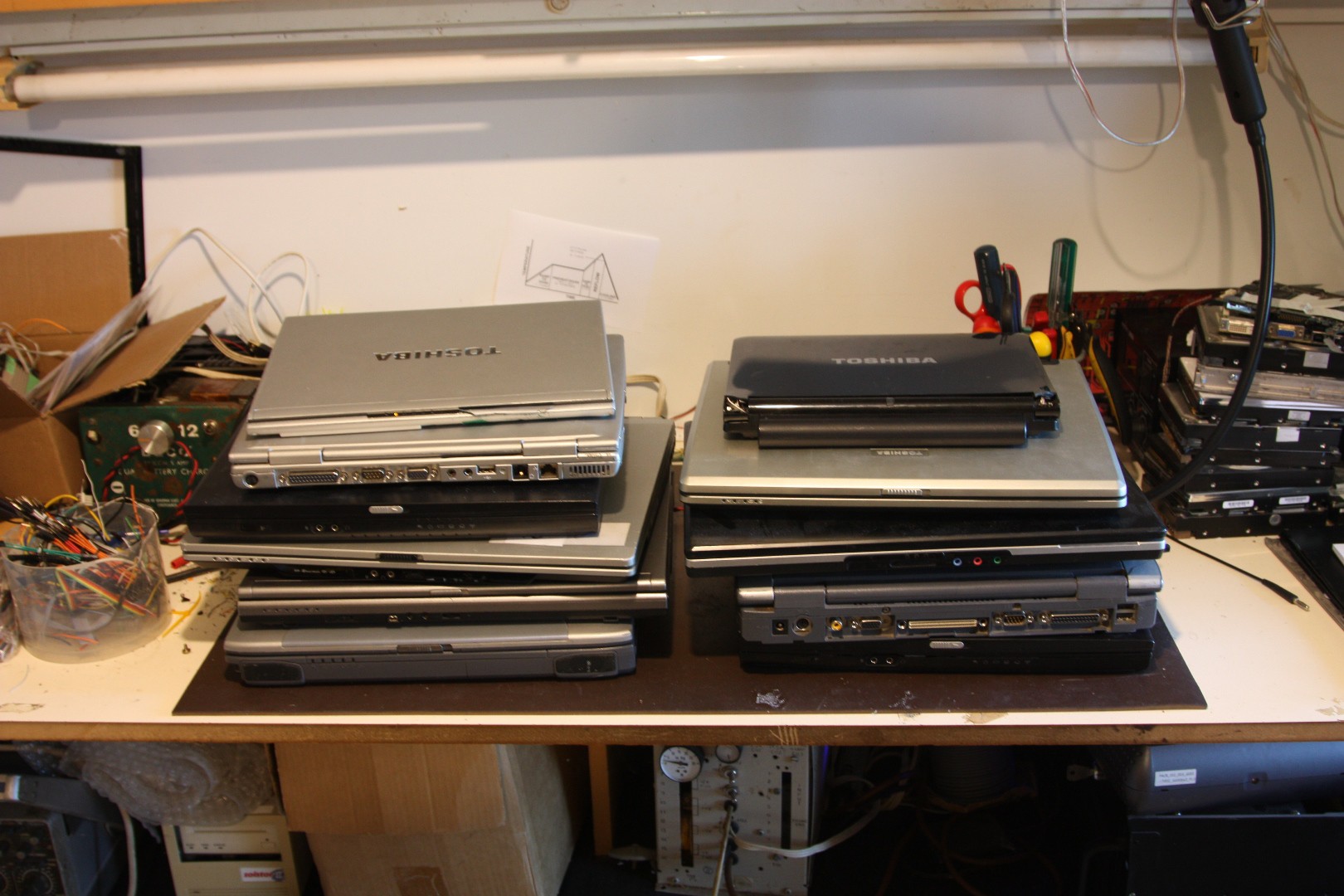
    So my Dad has a big collection of old laptops gathering dust, most of them running XP or older. I wondered whether it would be possible to extract the LCD out of one and perhaps use it with something like a Raspberry Pi? I remember seeing people wonder this on old forum posts in the past and the common answer was "it's not possible, they use LVDS".

    Times have changed since then, and it is indeed possible, and a lot easier than I thought it would be! To start off easy I decided to get a RIoT Board, based on an iMX6 Solo ARM A9 processor, which has a native LVDS interface!

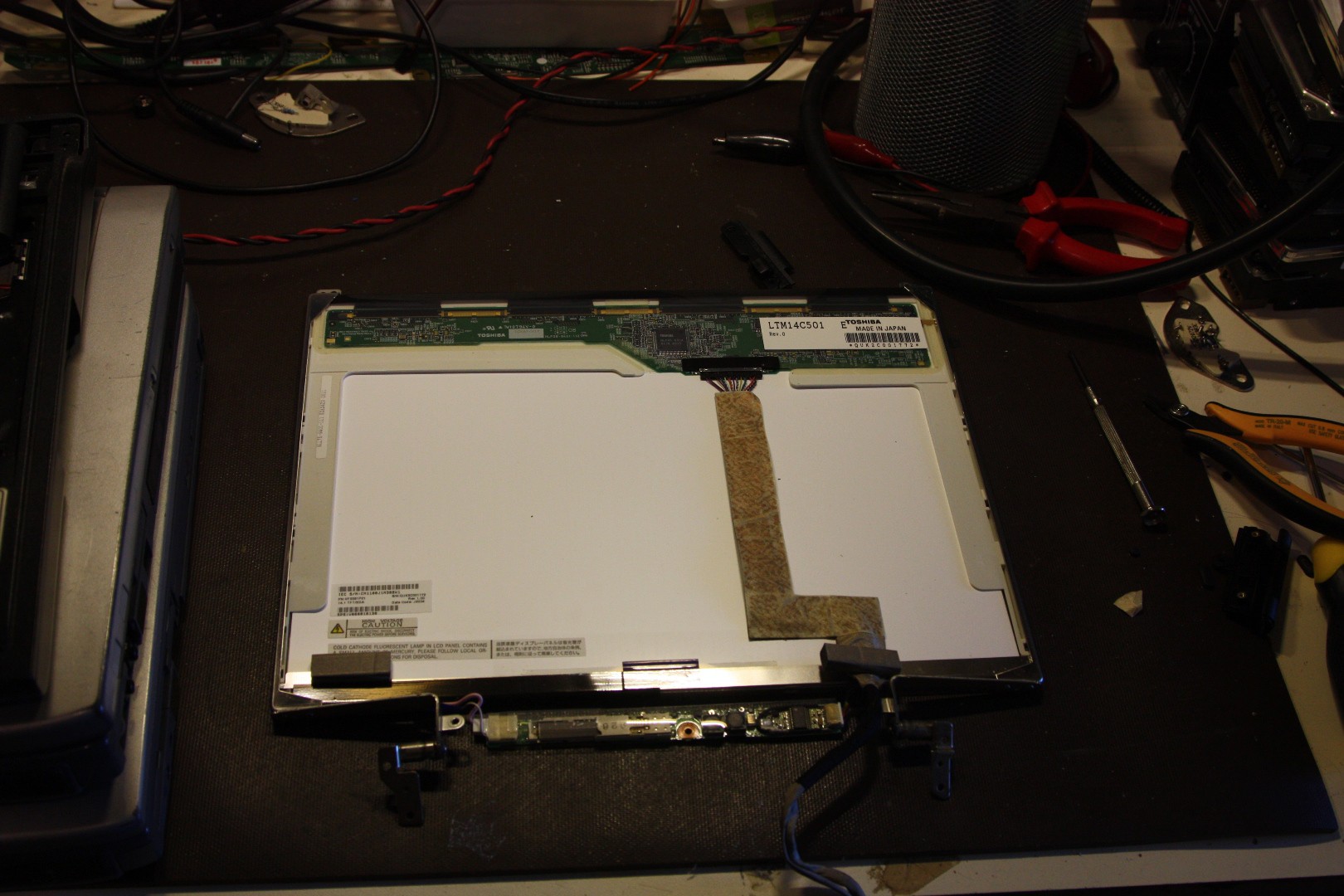
    To start off my experiment, I extracted an LCD panel out of a suitably broken laptop:

    It was fairly obvious which pins were power and LVDS pairs (LVDS signals are ALWAYS routed in close pairs, and may or may not be separated by a ground pin), but I didn't know which pairs were which. Luckily I managed to find a datasheet easily enough, which instantly revealed the exact pinout.

    The backlight driver wasn't quite so easy, but after a bit of probing around I got it to power up the fluorescent tube. Interestingly it only required 5V to power up.

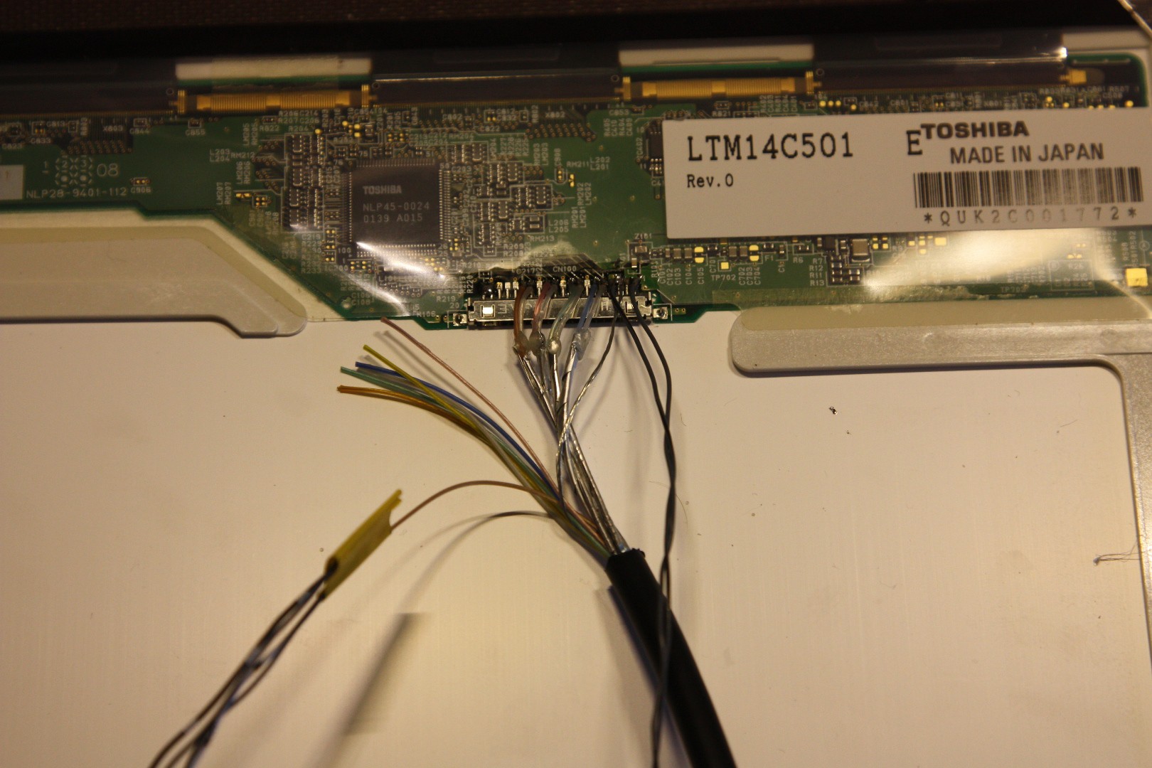
    The RIoT board provides its LVDS signals through a micro-HDMI connector (It is not actually HDMI!), so I chopped an old cable and soldered it directly to the panel (since the laptop was broken anyway):

    The other wires are for backlight dimming and a touch screen display, none of which are required to display an image.

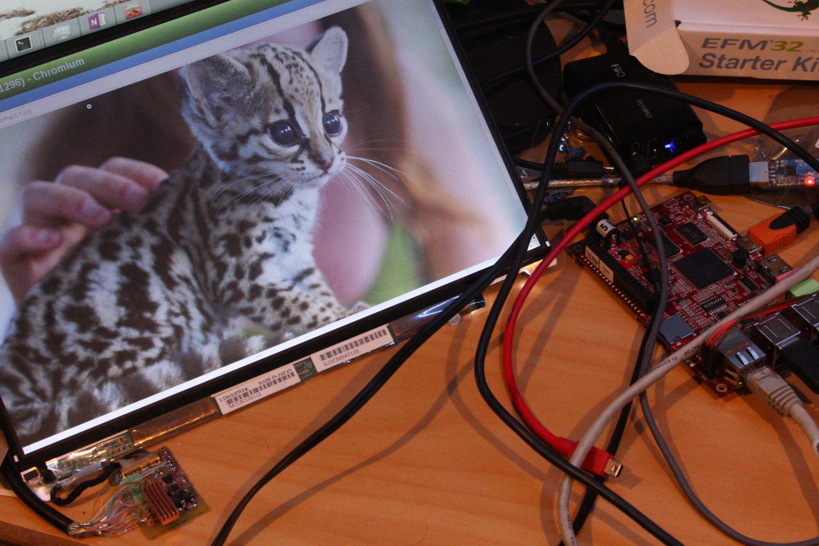
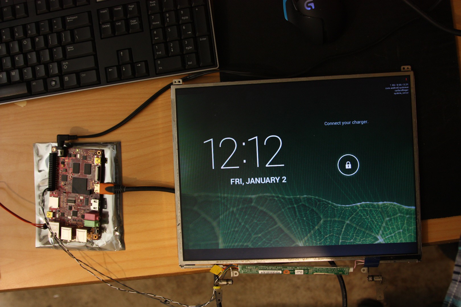
    And after reconfiguring the RIoTBoard to output video on the LVDS connector, success!

    It just so happened that the LCD panel matched the RIoTBoard's default output resolution, but it worked right out of the box first try!

    My next experiment is a lot more complex: I have a newer "transflective" LED-backlit LCD display out of an old Portege R500. These screens are special in that they are sunlight readable! But their connector is very very fine and the backlight requires +30V to drive, which makes things difficult. My post on this will be coming soon!

View all 4 project logs

Enjoy this project?

Share

Discussions

Sebastian wrote 05/30/2021 at 16:46 point

Hello, do you know some device to register the signal going to laptop's screen or to check if it's right? On my old laptop Asus X55VD I had much eyestrain when using Linux, while it was ok with preinstalled Windows. The same occurs with my new Dell Inspiron 3559 (with preinstalled Linux Ubuntu). There must be some pulsation or dithering. Other people reported a similar problem, it prevents some people from using Linux.

  Are you sure? yes | no

alexvladi1987 wrote 02/03/2021 at 06:08 point

hey not sure if you can help me but I have an lcd in my car navigation I wanted to find the pinout of it and replace the lcd with a video out hdmi or rgb any type 

I looked and couldn’t find any data sheets for the lcd or the navigation I have photos of the back of the lcd and of the part where it connects thanks 

  Are you sure? yes | no

shchoe444 wrote 02/27/2020 at 19:32 point

This is great project for many other DIY project!!!!

I have samsung ltm230hl08 display and I could not put work.... 

  Are you sure? yes | no

Koen van Vliet wrote 02/19/2020 at 12:00 point

Thanks for keeping this stuff out of the landfill. So much stuff gets tossed out these days.

  Are you sure? yes | no

Starhawk wrote 01/01/2020 at 20:27 point

Hello from the first day of 2020! Have you since discovered eBay and the Chinese sellers with their LVDS-to-[various common display connectors] converter boards? us$35ish each (YMMV if you live elsewhere, sorry) and almost entirely reliable... and if you get ePacket or "Standard SpeedPAK" (ugh!) shipping, you'll get it in about two weeks.

That said... the project documented here *is* a monumental effort, as documented, and worthy of great respect in every way. Well done!

  Are you sure? yes | no

Arya wrote 02/14/2018 at 17:17 point

This is a great writeup, thank you for documenting your reverse-engineering attempts so well!

  Are you sure? yes | no

lantramnamcodon wrote 10/10/2017 at 00:22 point

i have an 30 pins lvds lcd tv and the main board is broking,i use pcb800099 and use its lvds connection,it's also 30 pins but will it work if i connect them together?my pinout is different to your picture.

  Are you sure? yes | no

Jared Sanson wrote 03/13/2018 at 02:09 point

I don't know. You'll need to check the pinout of the TV LCD panel and the PCB800099 board. You can't assume that they'll have the same pinout. I haven't used that board so I can't really help you there, sorry...

  Are you sure? yes | no

Eduardo wrote 08/01/2017 at 17:21 point

I own a laptop with no "On Power Display" options in BIOS. I also would like to use this laptop to build a homemade HTPC. HDMI won't display either BIOS nor OS choosing options. So I think I should reverse all your adventure here: figure out a HDMI connector taking output signal from a LVDS laptop's motherboard connection.

Still not sure how to do it but know that all your work here will give me a lot of help.

Thank you very much for sharing.

What do you think about my project?

Do you have notice from somebody who made it already?


  Are you sure? yes | no

Jared Sanson wrote 03/13/2018 at 02:11 point

You want to do LVDS->HDMI? It should be possible. I've seen LVDS->eDP boards on Aliexpress, so a similar thing might exist for HDMI. Or you could use an LVDS->eDP board combined with a DP->HDMI converter.

Failing that, there should be chips that can do the conversion for you (but you'll have to make your own PCB)

  Are you sure? yes | no

RW wrote 03/02/2020 at 19:26 point

I've ran two broken screen laptops in the past and neither of those had a bios setting, but they remembered state from the function key switching after soft power down.

  Are you sure? yes | no

bigalmccameron wrote 06/07/2017 at 16:20 point

I bought an lvds to hdmi driver from China (of course) for an Ipad 1 screen. All the blacks show up as red so the screen looks really funny, screen was working fine when I removed it. Is this fixable?

  Are you sure? yes | no

Jared Sanson wrote 03/13/2018 at 02:07 point

It should theoretically be fixable, it sounds like you have one of the pairs swapped. Since you're seeing black/red, I'd try swapping the Pair0/Y0 polarity (contains mostly red bits).

  Are you sure? yes | no

fermin_mena wrote 06/03/2017 at 22:26 point

Buenas noches saludos desde chile excelente pagina. Aunque yo solo dedico a la reparacion de computadores. Necesito de su ayuda Tengo un cuaderno que me llego. El cual usa una pantalla led 13,3 30 pines. Yo tengo una pantalla led 13.3 40 pines led. Osea ambas son led La diferencia que una es de 30 pinos y la otra de 40 pinos. Estube mirando y buscando por todos los lados. Para aprovechar mi pantalla, ademas de ser escasa. En la actualidad, no hay información disponible.

Good night greetings from Chile excellent page. Although I only dedicate to the repair of computers. I need your help. I have a notebook that came to me. Which uses a led display 13.3 30 pins. I have a led display 13.3 40 led pins. Both bone are led The difference that one is 30 pines and the other of 40 pines. I was looking and looking all over the place. To take advantage of my screen, besides being scarce. At present, no information is available.

  Are you sure? yes | no

claudita olivia wrote 05/16/2016 at 07:54 point

Hello

I hope I have understod the purpose and scope of your project so I think you culd help me. I have a LCD from an old computer which numer is LP150X04. I bought a MT6820-B Universal LVDS LCD Monitor Driver Controller Board 5V 17"-42" New and I was told that would be compatible. When I connected it did not work, so I though the image would be so dark and hard to see after all it had not inverter included. I decided to buy an inverter (http://www.ebay.com/itm/401045944772?_trksid=p2057872.m2749.l2649&ssPageName=STRK:MEBIDX:IT )and a CCFL tester ( http://www.ebay.com/itm/141758477324?_trksid=p2057872.m2749.l2649&ssPageName=STRK:MEBIDX:IT )in order to provide power to the backlight of the panel. When I had everything connect it did not work, so I find the data sheet and I used a needle to modify the LVDS cable and matching the conections according the panel pin connector scheme as shown in the datasheet. The result was no image but the screen flickers and I realize when I plug the VGA to my laptop he screen flickers in other way. I hope you could help me. I am a new user so I do not how to send you some pictures.  

  Are you sure? yes | no

Jared Sanson wrote 05/17/2016 at 05:49 point

Interesting. You can send me a private message or e-mail (go to my profile page) and I'll see if I can help

  Are you sure? yes | no

Jorch.washington wrote 02/15/2016 at 06:29 point

Hi, i've been searching something like this, i have a couple of screens from broken notebooks (hp mini and acer aspire one) with 40 pins lvds connector. Im just amateur, dont know about electronics but im thinking that i can connect each cable into a vga adapter without a converter/board. I Had this idea because my lcd screens does not require more than 3.1v in pin # 2,3 & 4 and 5v in the pin 29 & 30. Also i found that the vga pinout (al least in my laptop) has 4 5v outputs. So my question to you is, if its possible? Have you tried this?  am i just writing nosense? Every answers are welcome! And thankyou so much in advance!

  Are you sure? yes | no

Jared Sanson wrote 02/15/2016 at 21:18 point

No it won't be possible. VGA is analog (each R,G,B colour is sent as a voltage) and LVDS is high-speed digital (The colours are encoded digitally and sent as 1s and 0s)

  Are you sure? yes | no

Jorch.washington wrote 02/16/2016 at 08:14 point

thankyou so much for your reply, i have been reading your detailed post about fpdlink and i was amazed about all your wisdom and the passion for sharing! Thank you so much again! 

  Are you sure? yes | no

cmduarte wrote 05/24/2015 at 15:25 point

Yes, please include your details or submit a site that they can be 'glommed' from, Thanks. I have about 6 different panels including one with built in touch screen that I would love to put into action.

  Are you sure? yes | no

Jared Sanson wrote 05/25/2015 at 10:54 point

Check out the links on the left of the page - I wrote a detailed article which you may find helpful :)

http://jared.geek.nz/2015/apr/driving-fpdlink-displays

  Are you sure? yes | no

Eric Hertz wrote 04/09/2015 at 08:22 point

Clever, determining the pinout by shorting the pairs and seeing the effect.

  Are you sure? yes | no

badger wrote 03/24/2015 at 20:41 point

Thanks for the suggestion on the HDMI/DVI to LVDS board. I've since found some ITX motherboards support LVDS so I plan to try and interface with one of those using a breakout PCB with backlight driver similar to yours. I've picked up a second-hand R600, a spare panel and spare R500/600 LVDS cable to mess around with. 

I think I may have an answer on why your breakout board wasn't successful. It seems some of these I-PEX connectors are micro-coaxial cables. To be honest I'm quite astonished by this given their tiny diameter but it could explain how they ended up shorted through to the case - I presume the outer conductor would be grounded. Maybe that's why the pairs aren't twisted in the R500 display cable too (I was expecting them to be). 

Where did you source the connector for your board? It looks like you re-used the cable from the laptop. As best I can tell the mating part is a "Cabline-SS" from diaachi seiko p/n 20374-035E-21 or 20374-035E-31.

  Are you sure? yes | no

Jared Sanson wrote 03/25/2015 at 08:50 point

Interesting, I wasn't aware you could get Mini ITX boards with LVDS! Also I do remember coming across references to the cable being micro-coaxial, but I find that hard to believe too. It would explain why lightly squeezing the cables with my sidecutters would cause the display to become corrupted! (This is how I was able to guess the LVDS lines) When I was cutting the wires I noted that the blue ones were stranded, and the black ones were solid core. Sounds like the best way to go is to create a breakout board for the connector like I did. Failing that, you could probably solder directly to the display.

I'm pretty sure it is a Cableline-SS (took me a while to find it) http://www.daiichi-seiko.co.jp/english/product/electronics/sgcconnector/cabline/CABLINE-SS.html

Sadly I wasn't able to find a good source of the connector, so I just un-soldered one from a broken laptop, and re-used the cable. Let me know if you find a source!

This might be a good source for the cables though:

http://www.alibaba.com/product-detail/For-Toshiba-R500-LCD-ribbon-cable_947123449.html 

  Are you sure? yes | no

badger wrote 03/15/2015 at 19:25 point

Really interesting project this one! I'm looking to build a ground control station for my multirotors and the R500 LCD looks ideal for outdoor use. In case you haven't found it already, I've managed to track down a data sheet. The pinout seems to match your PCB.

http://www.twscreen.com/media/pdf/M20120511110712880/LTD121EWEK-V05.pdf

Now I need to work out how to drive one from HDMI / Displayport / DVI!

  Are you sure? yes | no

Jared Sanson wrote 03/16/2015 at 06:05 point

Thanks!
Yeah it took me a while to find the datasheet too, and I was pretty happy to see it mostly matched my original pinout!


I have some pointers for driving such a thing from HDMI/DVI - I've found a company that make LVDS-HDMI adapter boards for around $35USD (although
currently out of stock): http://www.chalk-elec.com/?page_id=1280#!/HDMI-to-LVDS-converter/p/14647633/category=3094859
It should happily drive the R500 LCD, although I don't have one myself. If you connect the EDID lines on the R500 panel right through to the HDMI connector, then it should "just work" with any computer you plug it into! Their design is open-source too


The panel itself is pretty cool, although the viewing angle is a bit restricted. Polarized sunglasses help reduce the glare in full sunlight. You could also look
at the PixelQi on Adafruit, but it's only monochrome in sunlight and the
manufacturer's website seems pretty dead!

  Are you sure? yes | no

Similar Projects

Does this project spark your interest?

Become a member to follow this project and never miss any updates