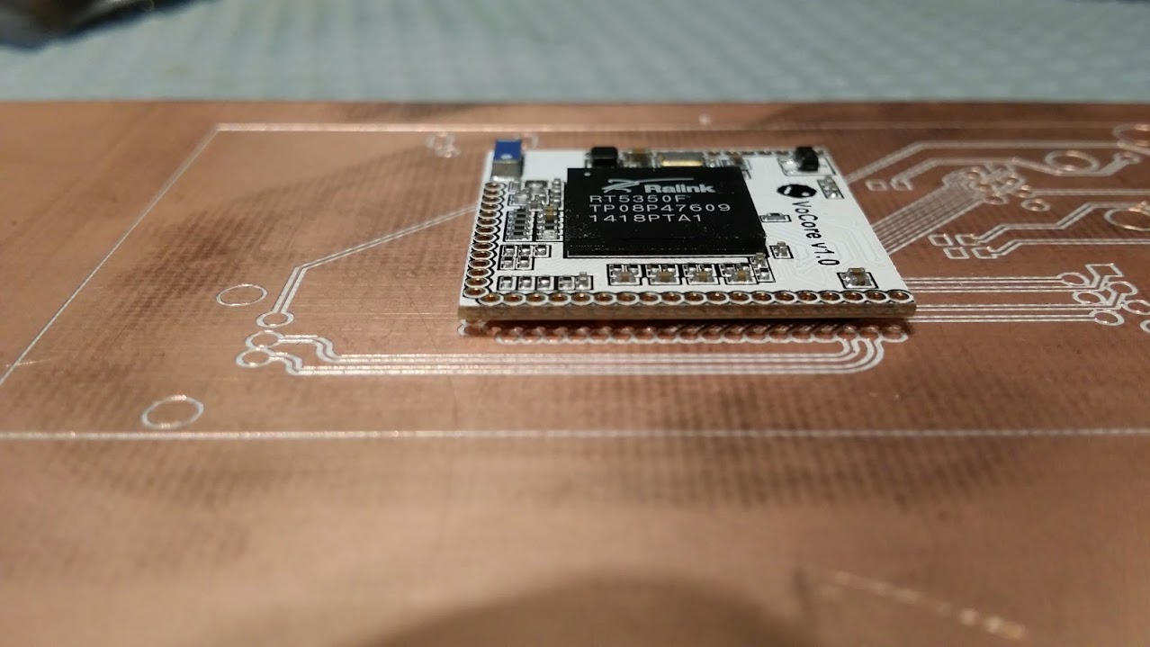
I've been recreating the vocore dock and vocore schematic since as in a lot of "open source" projects people often only give gerbers and pdf schematics, i realise why that is , but if your product is meant to interface to something else its nice to have the board available in a format you can actually use in a PCB layout tool. they're on my github and the NSL 032 svn. I Also mapped out the BGA part , since i couldnt find a bsdl for the rt5350f so did it the hard way.
anyway i started up the second badge, can only have two ethernets because the pins to the BGA aren't broken out, so that's a shame, also wondering why the phy ether0 leds aren't on the led's from the rt5350 pins.
did a test cutout on single sided and then after it was done, thought hmm i forgot to do the drills, then for some reason eagle/my pcb mills software is no longer importing the drills properly so i just said screw it and made sure they lined up, i'll put the board back when i figure out what happened in the eagle -> gerber -> mill software ... only takes a few minutes to cut outy a board , and i have these really nice single sided pcb blanks from all electronics.

for entirely no reason, some lowres closeup pictures of the board. sans holes,, which would be entirely useful right now.
ok so once i figure out whats going wrong in the excellon i'll drill these out, and mount the board with the 1.27mm headers. (note to self add teardrops )
the plan is two ethernet ports, wifi , usb host, uart ( with pads for a dare i say it, ft232r ) and break out the other pins and we're cooking with gas,,
 charliex
Discussions
Become a Hackaday.io Member
Create an account to leave a comment. Already have an account? Log In.