 sei
seiI decided to pack the electronics on two different boards, one for the microcontroller and one for the motor drivers. Turns out this was a wise move, because I recently switched the motor drivers from A4988's to TMC2209's, specificly SilentStepSticks from Watterott and they are awesome! They are much quieter and I'm quite happy with the stepping speed they offer. I use them in conjunction with Protector Boards, because the power-on is a bit complicated without them.
The controller board looks like this:
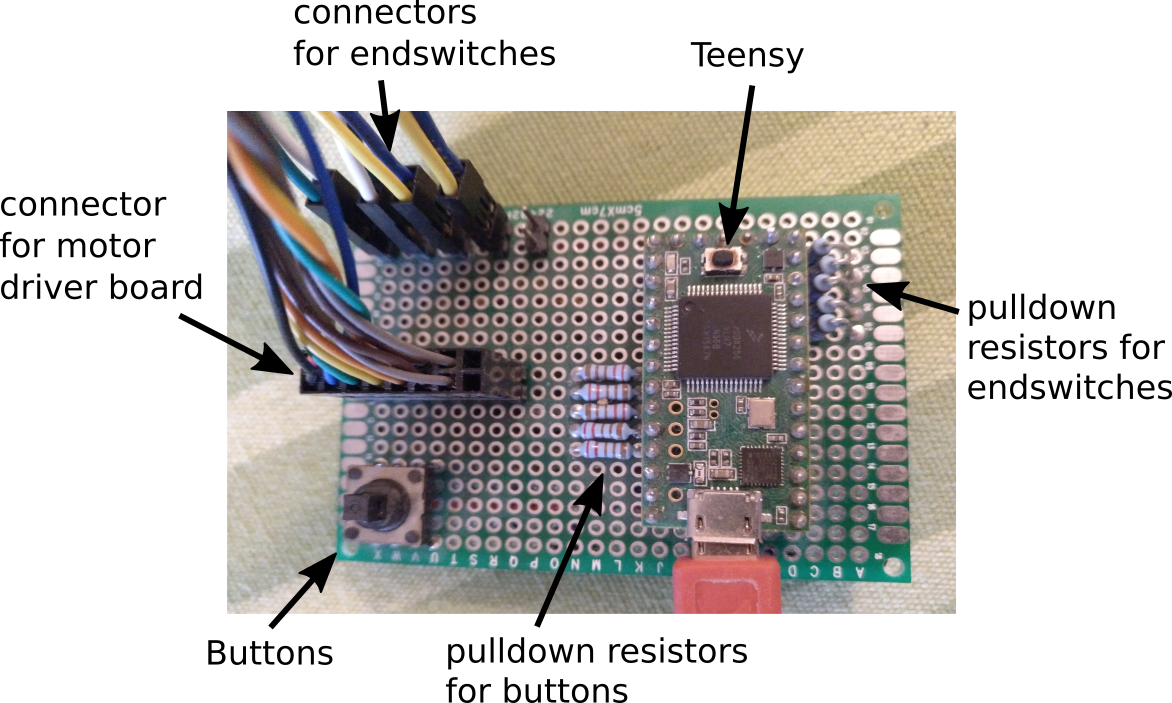
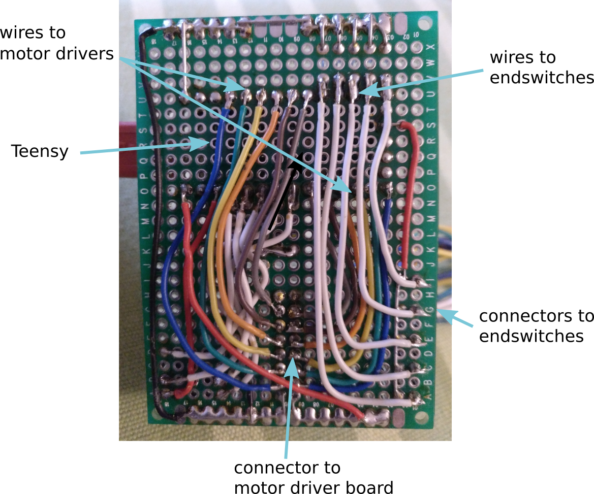
There is one big connector to connect the microcontroller with the driver board, and several small connectors for the endswitches.
The driver board looks like this:
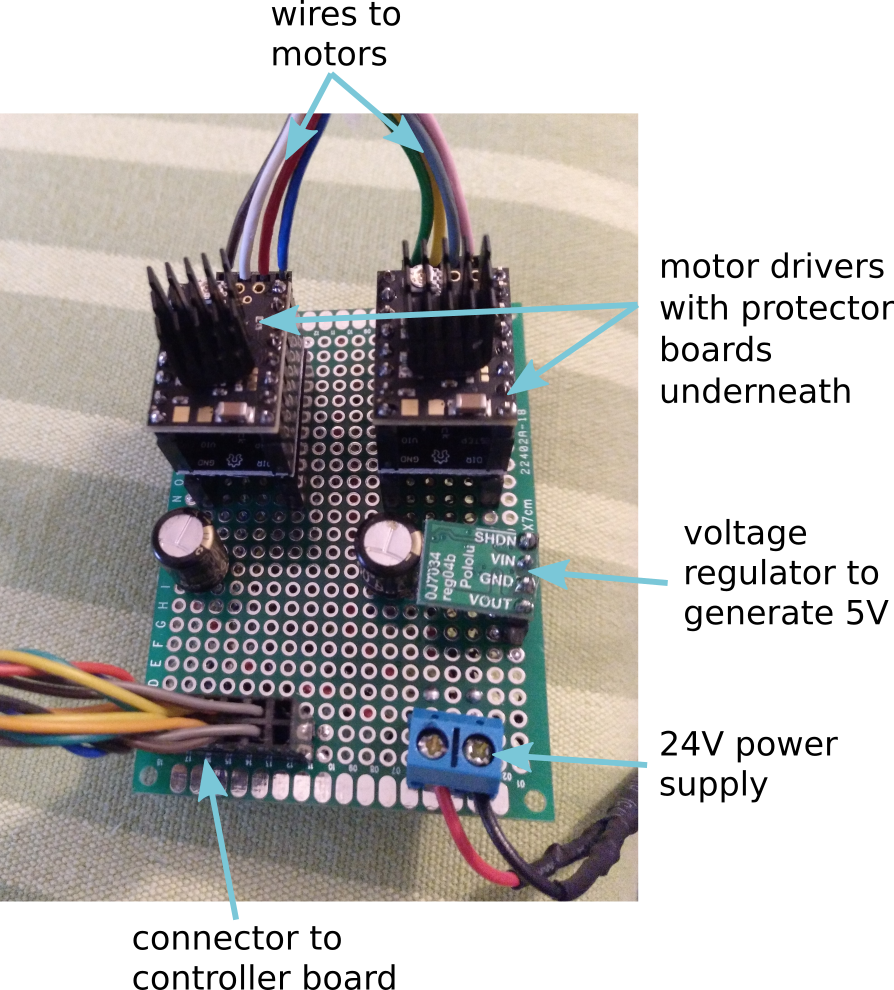
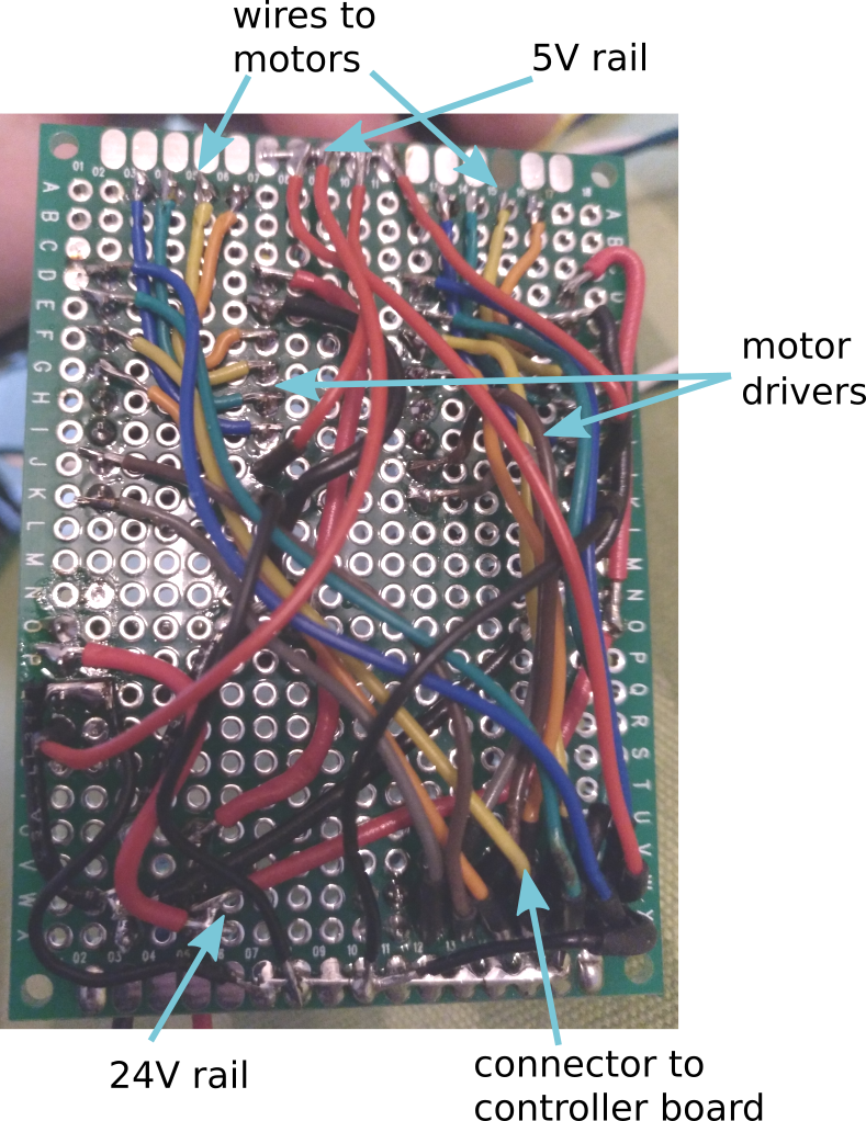
The motor drivers get fed by a 24V power supply. A voltage regular is used to generate 5V from the power supply and feed the driver logic and the teensy. The capacitors are necessary to smooth the voltage from the spikes generated by the motors.
Discussions
Become a Hackaday.io Member
Create an account to leave a comment. Already have an account? Log In.