Mechanical design
my main goal in this project was to demonstrate the automatic steering correction for a car driving reverse with a trailer.
for that I needed a powered car with a trailer where I can measure the angle between them.
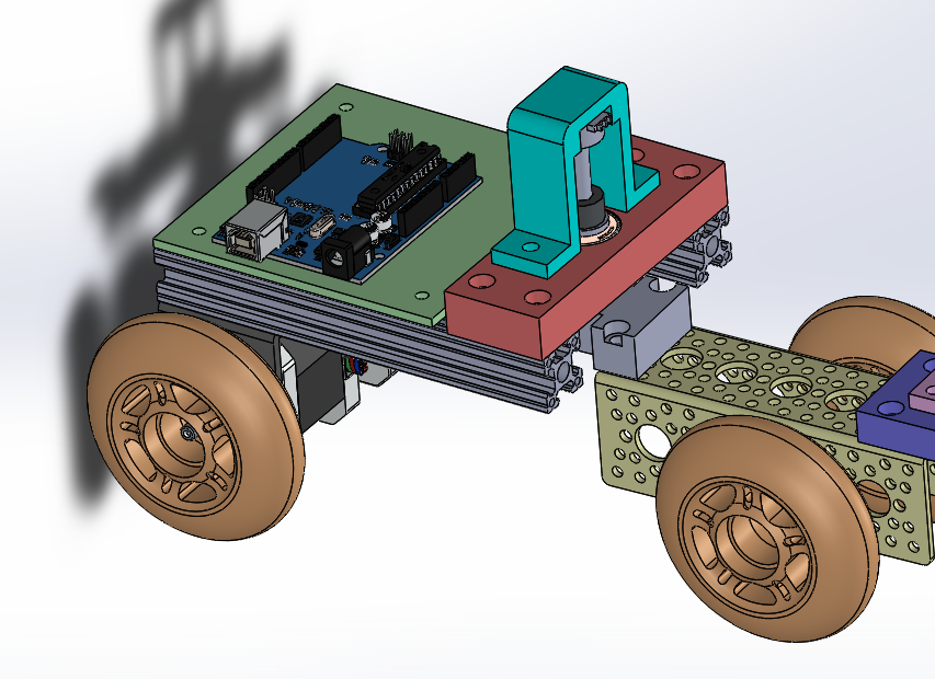
I designed A car using some very basic elements:
aluminum frame to hold the motors
two stepper motors (nema 17)
75mm roller blades wheels
Poly carbonate plate to hold the electronics
608zz bearing
M8X30 bolt as axle
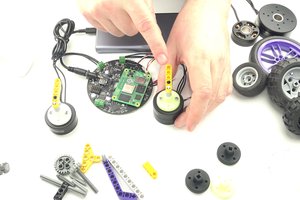
a single turn potentiometer to measure the trailer angle
3D printed parts
Steering
As you can see in the the pictures, I use stepper motors to drive each of the wheels. in order to control the steering angle I needed to drive each motor with a different velocity according the rule:
Control
to control the vehicle I need to compute the desired steering angle according the measured trailer angle and required driving angle (from remote control). the key feature of the problem is that for every trailer angle there is a steering angle that applying it will keep the trailer angle constant.
actually, it is not that simple since this is not a stable system, so even to keep the trailer in a constant angle requires constant corrections. this what makes the problem difficult to a human driver but easy to an automatic one.
from here it is just some math to get the numbers.
I start with the kinematic model of a single trailer as shown in the picture below:
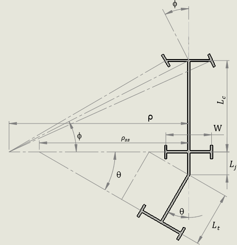
where:
By measuring the trailer's angle, I can calculate the coordinated turning radius
and the steering angle required to keep the trailers angle constant:
now here is the interesting part, steering angle larger than that will
cause the trailer angle to decrease and vice versa.
so a simple control rule will be:
where K is again factor that I tuned until receiving best performance.
the arduino constantly measures the trailer's angle ( as an analog voltage on the potentiometer) and calculates the steering command as mentioned above.
Watch on youtube:


 Artur Majtczak
 Corsix
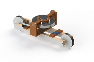
 Mateus Abreu
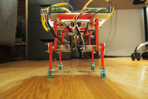
Very cool! Good job!