I got a chance to power-up the first divide-by-two and it actually works!
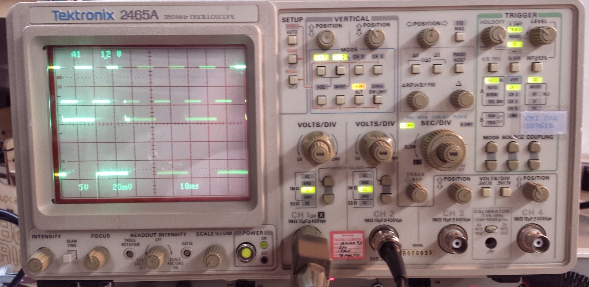
I've got both output wires soldered on the wrong place, but when I scope the right place, I can see it flipping and flopping! Top trace is a 9V 60Hz signal from the signal generator. Lower trace is one end of the divide-by-two running at 30Hz just as expected. The amplitude isn't right since I've got the wire on the wrong place, but it's working.

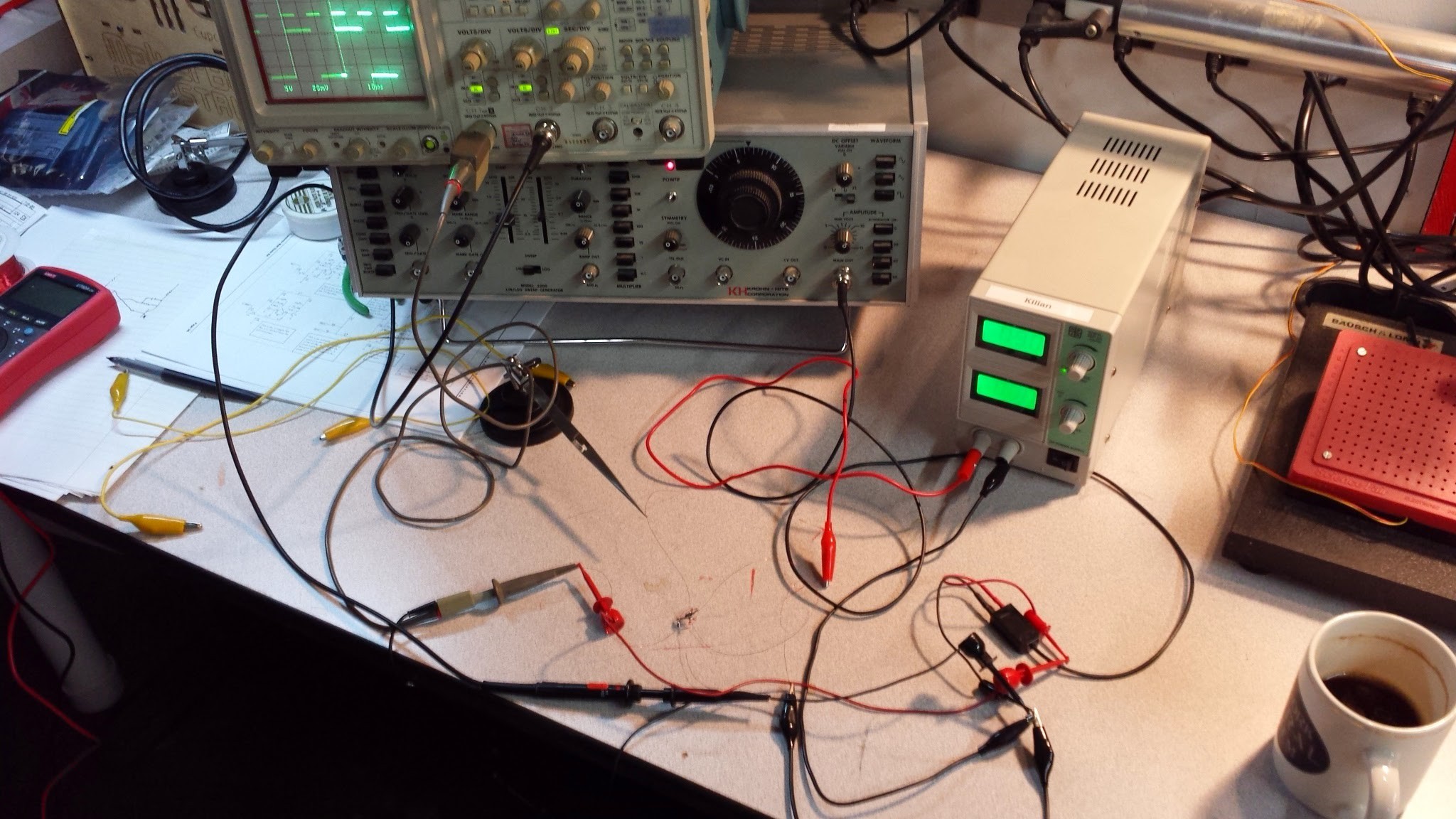
Here's the monster wire-nest of testing:

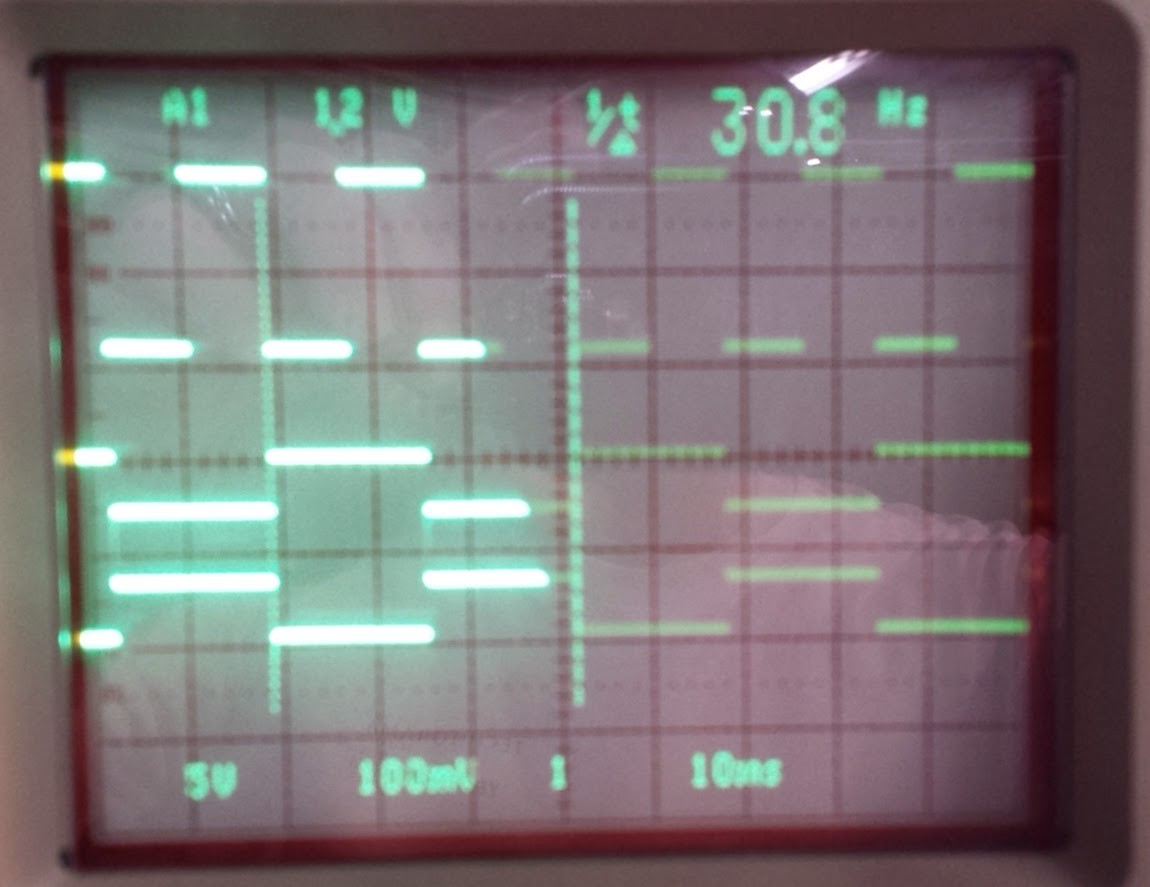
Here's a three-trace image showing the input at 60HZ, the normal output at 30HZ and the inverted output at 30HZ:

Sorry about the photo quality. I'll do better in the future.
So, IT'S WORKING!!! Now I'm really in trouble.
 Alan Kilian
Discussions
Become a Hackaday.io Member
Create an account to leave a comment. Already have an account? Log In.